
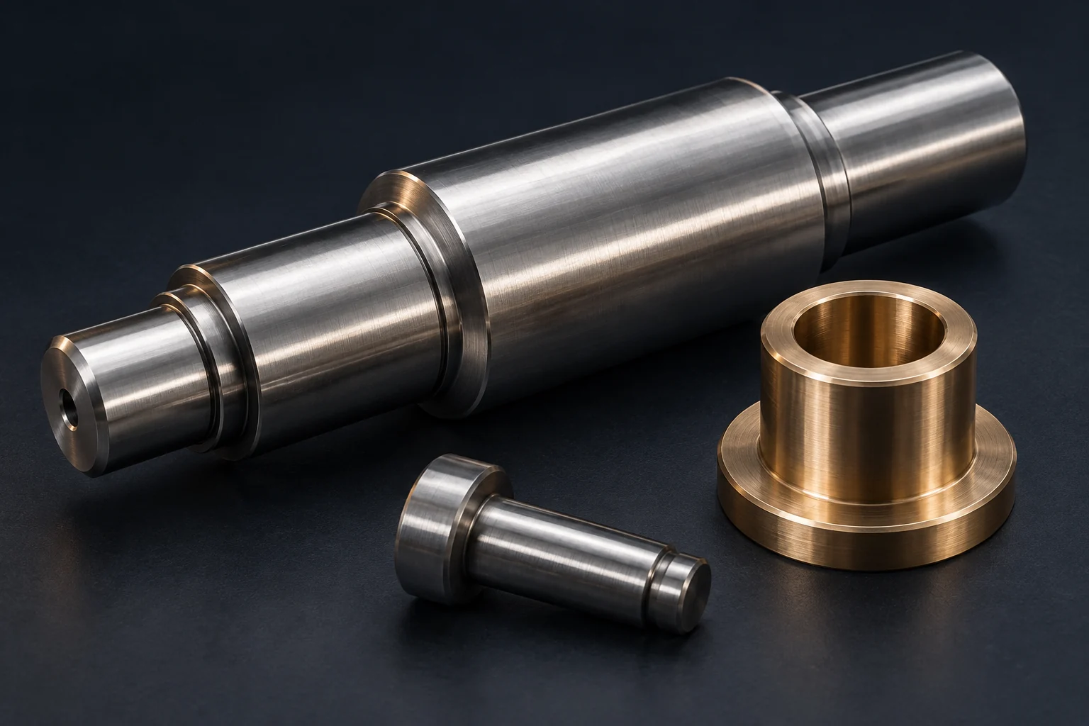
 01 / CORE APPLICATION
Automation & motion
Will the mating parts fit and move as intended?
- Stepped shafts
- Flanged guide bushings
- Shoulder locating pins
THE CHENGSHUO COMPONENT CASEBOOK
Find a part close to yours. Explore its geometry, the questions that shape its manufacture, and what your team needs to specify.

COMPONENTS BY THE PRODUCT YOU BUILD
Each collection connects the forms you may need with the features your engineering, sourcing and quality teams need to define.
01 / CORE APPLICATIONAutomation & motion
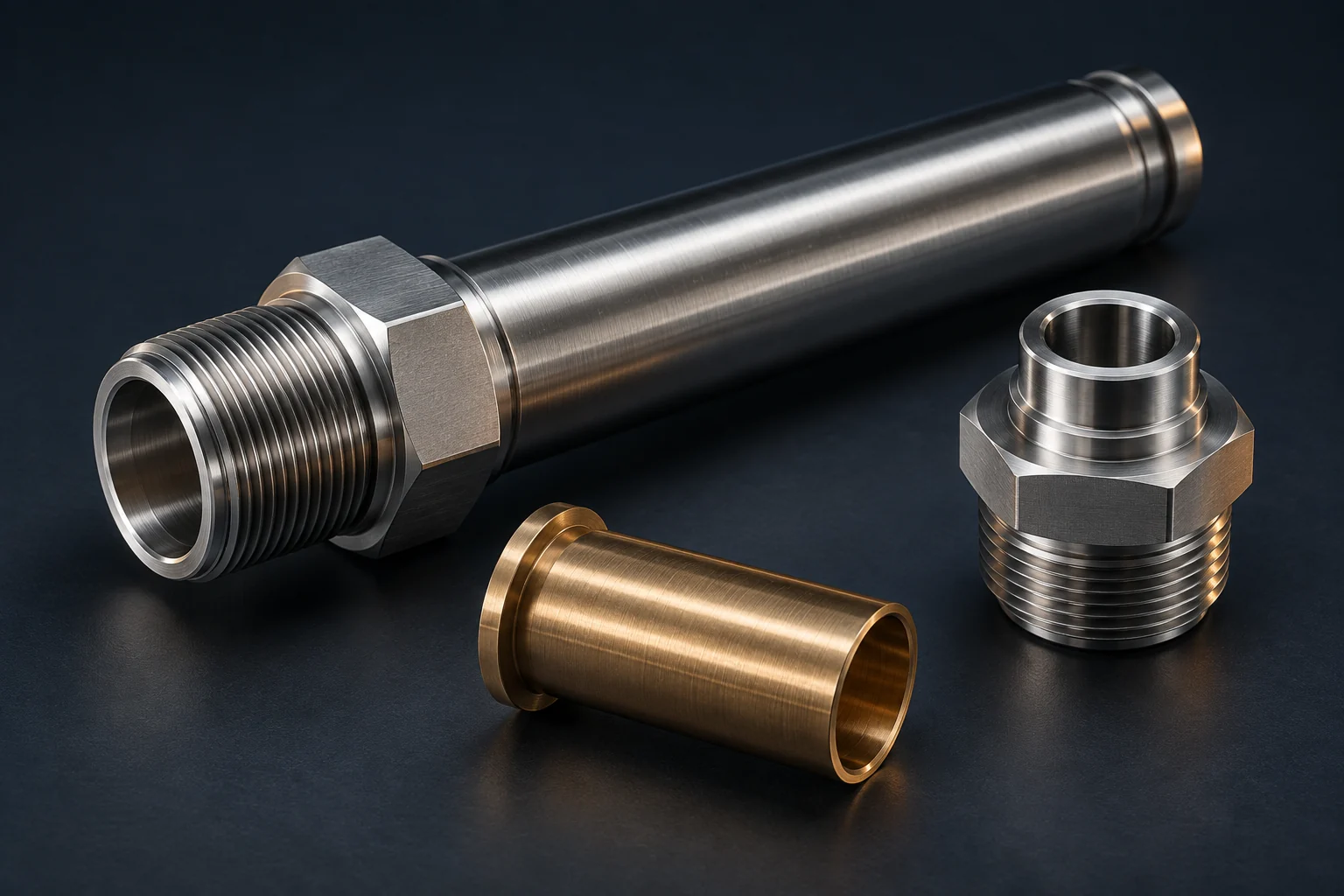 02 / CORE APPLICATION
Instruments & sensors
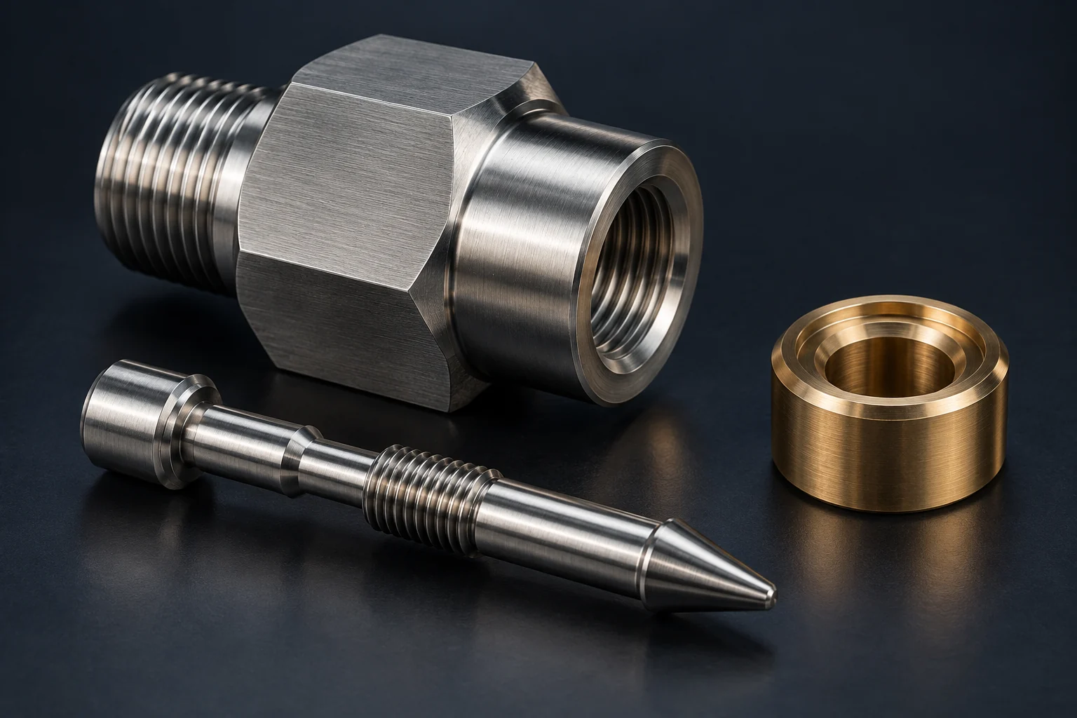 03 / CORE APPLICATION
Fluid connections
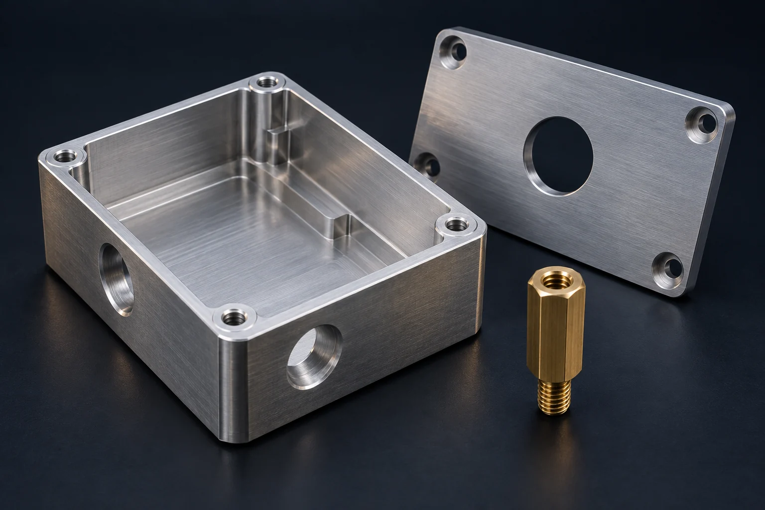 04 / ADDITIONAL SCOPE
Electronic hardware
Illustrative component forms · manufacturing review required. Each collection links to relevant photographed references.
FROM ORDER TO RECORDED DELIVERY
Explore three anonymized Chengshuo order records, then define the inspection and handover requirements for your own parts.
All delivery recordsRECORDED DELIVERY / CS-D01
Completed order · deliveredA screw-stud order with SS304 recorded in the order note and 2,400 pieces in the order scope.
RECORDED DELIVERY / CS-D02
Completed order · deliveredA component described as PIN in the order record. The platform marks the order complete, and carrier tracking records delivery.
RECORDED DELIVERY / CS-D03
Completed order · deliveredA custom-component order recording 441 pieces across 11 quantity lines grouped under 10 product listings.
Anonymized record summary. Company Alibaba order record · reviewed 16 Sep 2026. Order and tracking statuses do not establish dimensional inspection results, customer quality acceptance or the customer’s end-use.
FROM COMPONENT TO PROCUREMENT BRIEF
Component presentations with original photographs and individual reviews of geometry, specification and acceptance. Narrow the collection to the project you are working on.
32 product cases
 AI-assisted studio view
A working guide section and end fixing interface. Separate the guide fit, working length and thread requirements.
 AI-assisted studio view
Multiple diameters, shoulders and grooves in one component. Review the fits and references that locate your assembly.
 AI-assisted studio view
Stepped brass components with locating and contact regions. Define mechanical fit, surface condition and any required electrical tests separately.
 AI-assisted studio view
Turned body sections, collars and narrow grooves. Connect the feature positions to the component’s mating and retention requirements.
 AI-assisted studio view
Small turned sections and shoulders for positioning and insertion. Review the mating fit, entry edges and handling requirements.
 AI-assisted studio view
A formed support with machined interfaces. Separate the casting envelope from the seats and mounting features requiring final machining.
 AI-assisted studio view
An extended internal envelope with a stepped collar. Review insert clearance, mounting stop and closure interfaces.
 AI-assisted studio view
A bore, axial stop face and radial fixing feature. Review the locating fit and how the collar is retained.
 AI-assisted studio view
Bore, wall section and secondary openings. Review end conditions, hole positions and edge treatment as one component.
 AI-assisted studio view
Annular parts for spacing and seating. Define stack height, contact faces and the clearance around the central opening.
 AI-assisted studio view
Bore, outside diameter and flange interfaces for custom assemblies. Review how the sleeve locates and supports the mating component.
 AI-assisted studio view
Contact faces, central openings and specified relief details. Define the section and edge condition your assembly needs.
 AI-assisted studio view
Bored bodies with external grooves and stepped ends. Connect the internal fit to the features that retain and locate the joint.
 AI-assisted studio view
Bore, side access and textured grip features. Establish the connection geometry and the requirements at each functional interface.
 AI-assisted studio view
Thread engagement, outer recesses and a seating face. Define the mating thread, tool access and final finishing condition.
 AI-assisted studio view
A smooth shank, extended thread and tool-engagement head. Distinguish grip length from the thread that joins the mating part.
 AI-assisted studio view
A central thread combined with a mounting flange. Review thread engagement, seating contact and the mounting-hole relationship.
 AI-assisted studio view
External threads, shoulder seats and cross holes. Review mating engagement, installation access and edges inside the passage.
 AI-assisted studio view
Slim enclosures with connector openings. Coordinate the port cutouts, board position and end interfaces before machining review.
 AI-assisted studio view
Box geometry, side openings and mounting details. Check board clearance, service access and closure requirements together.
 AI-assisted studio view
Recessed seats meet a shaped exterior. Review internal clearances, assembly access and the surfaces that remain visible.
 AI-assisted studio view
Long internal cavities and shaped exterior surfaces. Separate the assembly fit, grip profile and visible finishing requirements.
 AI-assisted studio view
A central bore, repeated holes and annular seating face. Specify the common datums and the mounting relationship.
 AI-assisted studio view
Bores, curved slots and hole patterns on a mounting face. Define the locating reference and adjustment features.
 AI-assisted studio view
A stepped base and angled upper body. Relate the front openings to the mounting reference and assembly direction.
 Original workshop photograph
Clear covers with closure and contact features. Specify the mating interface separately from the viewing and cosmetic surfaces.
 AI-assisted studio view
Turned bodies with a secondary milled slot. Review the slot location, contact edges and relationship to the turned axis.
 AI-assisted studio view
Reference faces, pockets and multiple holes. Build the machining and inspection brief around the features that position your assembly.
 AI-assisted studio view
Attachment faces and fastening openings across an angled form. Review the locating surfaces and assembly access.
 AI-assisted studio view
Repeated holding positions on a shared fixture. Define position references, loading access and the interfaces needing individual checks.
 AI-assisted studio view
Formed outer geometry with machined contact regions. Define the holding surfaces, mounting interfaces and casting scope.
 AI-assisted studio view
Machined mating features around an open envelope. Review datums, access and the relationships that locate the supported part.
Try a broader term or reset the filters. You can also send your drawing for a component-specific review.
NEW / ENGINEERING CONCEPT COLLECTION
Purposeful component forms for automation, sensors and fluid equipment. Explore the geometry and buying decisions, then develop your own drawing-led brief.
20 engineering concepts shown

AI-generated engineering concept
Automation & motion
Two close-fitting round pins can make a fixture difficult to load when hole spacing varies.
Relieved locating head · Controlled contact lands · Shouldered mounting shank
Feasibility and acceptance require your drawing.

AI-generated engineering concept
Automation & motion
A thread gauge can pass even when the insert damages the host or moves under assembly load.
Internal female thread · External knurled grip bands · Insertion lead and relief
Feasibility and acceptance require your drawing.

AI-generated engineering concept
Automation & motion
A correct overall length can still leave a gap or unwanted contact if the shoulder and mating seats are not defined.
Concentric through bore · Reduced locating pilot · Controlled shoulder and end faces
Feasibility and acceptance require your drawing.

AI-generated engineering concept
Automation & motion
A bore that fits before tightening may behave differently after the clamp screw is loaded.
Single radial clamping split · Transverse clamp-screw hole · Bored hub and mounting flange
Feasibility and acceptance require your drawing.

AI-generated engineering concept
Sensors & instrumentation
A retaining ring may thread into the barrel yet contact the lens incorrectly or obstruct the intended aperture.
Fine external thread · Opposed spanner slots · Annular retaining contact land
Feasibility and acceptance require your drawing.

AI-generated engineering concept
Sensors & instrumentation
The shell can meet its outside dimensions while the panel, locking hardware and insert do not align.
Panel-mount threaded neck · Wrench shoulder and orientation flat · Internal insert locating seat
Feasibility and acceptance require your drawing.

AI-generated engineering concept
Sensors & instrumentation
Plating, termination geometry and insulator fit can change an otherwise acceptable turned-contact interface.
Solid turned mating tip · Concentric insulator locating shoulder · Rear termination cup
Feasibility and acceptance require your drawing.

AI-generated engineering concept
Sensors & instrumentation
A holder can pass a bore check yet locate the ferrule at the wrong depth or stress it during assembly.
Ferrule receiving bore · Axial locating shoulder · External mounting pilot
Feasibility and acceptance require your drawing.

AI-generated engineering concept
Fluid control & equipment
The same tip length can produce a different relationship to the seat if taper definition and axial travel are unclear.
Controlled metering taper · Guided stem journal · Adjustment thread and shoulder
Feasibility and acceptance require your drawing.

AI-generated engineering concept
Fluid control & equipment
A fitting can assemble mechanically while an uncontrolled burr or damaged sealing face compromises the intended flow path.
Central bolt-eye passage · Parallel annular sealing faces · Threaded side connection
Feasibility and acceptance require your drawing.

AI-generated engineering concept
Fluid control & equipment
A nominally matching thread does not establish that the internal shoulder, gland and seal stack are compatible.
Internal connection thread · Annular gland-retaining shoulder · Hexagonal wrench interface
Feasibility and acceptance require your drawing.

AI-generated engineering concept
Fluid control & equipment
A visible cone does not define the contact band, installed position or leakage behavior of the valve.
Recessed conical seating surface · Concentric flow passage · External locating land and flange
Feasibility and acceptance require your drawing.

AI-generated engineering concept
Automation & motion
A hub can fit the shaft diameter yet sit at the wrong angle or axial position.
D-flat drive interface · Stepped bearing journals · Axial locating shoulder
Feasibility and acceptance require your drawing.

AI-generated engineering concept
Automation & motion
A pin can pass incoming size checks while the cross-hole edge or installed fit interferes with the mating assembly.
Axial through bore · Radial cross hole · Shouldered pivot journal
Feasibility and acceptance require your drawing.

AI-generated engineering concept
Automation & motion
Thread fit alone does not establish pin travel, spring space or a reliable retention method.
External mounting thread · Internal spring cavity · Reduced front opening
Feasibility and acceptance require your drawing.

AI-generated engineering concept
Sensors & instrumentation
Overall length and drilled depth can look acceptable while the sensor has the wrong insertion space or end contact.
Blind axial sensor bore · Closed sensing-end wall · Mounting shoulder
Feasibility and acceptance require your drawing.

AI-generated engineering concept
Sensors & instrumentation
A cap can screw into place while trapping an internal component or compressing the seal against the wrong surface.
Closed cup-shaped end · External closure thread · Internal clearance pocket
Feasibility and acceptance require your drawing.

AI-generated engineering concept
Sensors & instrumentation
The mounting thread can be correct while the cable or sealing insert is mismatched to the internal passage.
Hexagonal wrench flats · Threaded mounting section · Stepped cable passage
Feasibility and acceptance require your drawing.

AI-generated engineering concept
Fluid control & equipment
Acceptable hole sizes do not establish the intended overlap, sliding behaviour or internal edge condition.
Axial spool bore · Radial port pattern · Outer locating shoulders
Feasibility and acceptance require your drawing.

AI-generated engineering concept
Fluid control & equipment
A hose-tail diameter alone does not define tube fit, assembly damage or retention inside the device.
Rounded hose-barb profile · Axial through passage · Shoulder and retaining groove
Feasibility and acceptance require your drawing.
Try all concepts or another application.
AI-generated geometry studies, not photographed production or completed customer projects. Each concept includes a manufacturing review brief; specifications are agreed from your drawing.
Explore all new component referencesGO DEEPER INTO THE REQUIREMENT
Explore cross-component guides for fit, threads, cleanliness, inspection and repeat orders.
FROM EXAMPLE TO YOUR REQUIREMENT

Use an example to explain your idea.
Your own drawing defines the final specification.