Internal-threaded guide pillar
A stainless steel guide pillar with a long cylindrical body and stepped end features. Define the guide diameter, shoulder position and thread engagement for your drawing.
Explore componentGuide. Locate. Transmit.

Diameters, shoulders and end features that locate the assembly.
Explore 22 examples
20 component examples

A stainless steel guide pillar with a long cylindrical body and stepped end features. Define the guide diameter, shoulder position and thread engagement for your drawing.
Explore component
A stainless steel shaft with diameter changes, shoulders and circumferential grooves. Define the mating fits and the surfaces that control alignment.
Explore component
Brass pillar and contact forms with several diameter steps. Share the mating dimensions, engagement length and electrical requirements for your own component.
Explore component
A stepped shaft identified as copper in the source, with collars and narrow grooves. Specify the actual alloy and mating diameters in the drawing.
Explore component
A slender brass pin with stepped diameters, made using an automatic-lathe process. Start your review with the locating diameters and shoulder positions.
Explore component
An aluminum support column combining a central stem with a broad mounting form. The published process combines die casting and CNC machining.
Explore component
A relieved locating-pin concept for two-hole fixtures: define the active contact direction, mounting fit and loading clearance before ordering.
Explore component
A turned center-contact concept with a solid mating tip and rear termination cup: review the contact diameters, insulator seat and finished surface together.
Explore component
A slender metering-stem concept: define the taper profile, guided diameter and adjustment interface against the actual valve seat and travel.
Explore component
A stepped spindle concept for compact drives: connect the D-flat, bearing journals and shoulder positions to the mating hub before releasing a drawing.
Explore component
A hollow pin concept for pivoting mechanisms, with an axial bore, a cross hole and a locating shoulder to discuss together with the mating bushing.
Explore component
A hose-tail stem concept with a through passage, rounded barbs and a separate retaining interface. Review the tubing contact and body retention as two connected assembly tasks.
Explore component
A stainless steel poppet reference for compact check valves. Review the cone-to-seat relationship, guide diameter and spring seat against the complete valve design.
Explore component
An offset shaft reference for timing-belt tensioner assemblies. Define how the eccentric journal moves the roller, how the setting is locked and which surfaces locate the shaft before reviewing manufacture.
Explore component
A guide-rod reference for spring-return and clamping mechanisms. Coordinate the sliding section, spring seating features and available travel against the actual spring and housing.
Explore component
A worm-shaft reference for compact reduction drives. Treat the worm profile, mating wheel and bearing journals as one review, with the required gear geometry defined by your drawing.
Explore component
A grooved turret and stepped tail for custom solder termination points. Set the panel or board fit, usable soldering geometry and finish requirement before sample review.
Explore component
A slotted contact form for drawing-based power connector projects. Review the contact diameter, slot geometry and termination end together with the mating socket.
Explore component
A turned plunger component for spring-loaded test contact designs. Review tip shape, guide fit and retention shoulders against the barrel and travel envelope.
Explore component
A cylindrical pin with a retaining groove for custom industrial assemblies. Review the mating bore, clip geometry and axial stack-up before approving samples.
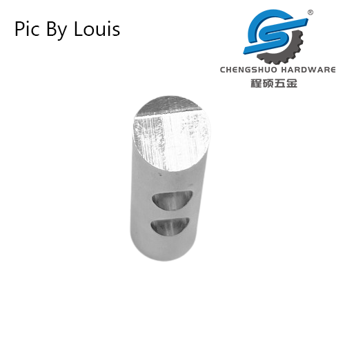
Explore componentAn aluminum connection-component reference from Chengshuo’s Louis-002 product listing. The photograph shows a cylindrical body, a flat end feature and two side openings. Use these interfaces to prepare your own controlled drawing and supplier enquiry.
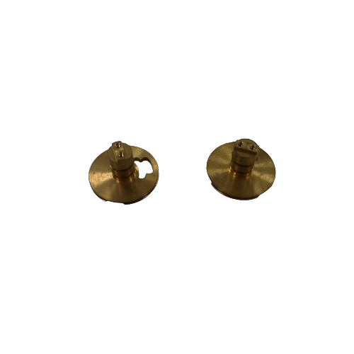
Explore componentA photographed brass component series from Chengshuo’s check-valve product reference. The two forms show broad discs and projecting central stems, with a cutout in one disc. Use the component geometry to define your own mating-seat and guide requirements.
Explore componentWHAT DEFINES YOUR VERSION?
Use these examples to explain the geometry. Include a current dimensioned drawing to define the actual part.
Mark the diameters that enter a mating bore and state whether the joint must slide, rotate or hold its position. Keep a fit requirement separate from a non-functional relief diameter.
A stepped shaft can be the correct size at each section and still need an alignment requirement. Identify the datum axis, the relevant surfaces and the agreed method for checking runout or straightness.
Show shoulder locations, groove widths and end details clearly. Include the required edge condition where a pin enters another component, and flag any surface that must remain free of burrs.
FROM EXAMPLE TO YOUR REQUIREMENT
Use an example to explain your idea.
Your own drawing defines the final specification.
ENGINEERING KNOWLEDGE
Define shaft clearance, bushing retention and inspection condition separately, then connect size limits, geometric controls and sample checks to the assembly.
Which Features Matter on a Shaft or Pin?Review mating diameters, datums, shoulders, threads and edges before releasing a small turned component for quotation.
A Useful Inspection Record for Small Turned PartsBuild a report that connects each shaft, sleeve or pin measurement to the drawing revision, sample identity and agreed inspection method.