

 AI-assisted studio view
cs-product-031
Sensor base sleeve
A stainless steel sleeve with a long tubular body and stepped end features. Review the sensor envelope, mounting interface and required sealing details for your design.
Explore component
Support the interface.
Source the sleeve, bushing or ring around the interface that actually locates your assembly. Define bore, outside surface and locating face together, then agree the material, delivered condition and inspection records in a drawing-based enquiry to Chengshuo.
Explore 17 examples
17 component examples
AI-assisted studio viewA stainless steel sleeve with a long tubular body and stepped end features. Review the sensor envelope, mounting interface and required sealing details for your design.
Explore component AI-assisted studio view
Compact collars with a central bore and radial fixing features. Define the shaft diameter, axial location and fastening method before specifying your version.
Explore component AI-assisted studio view
Stainless steel tube forms with open bores. Define the wall thickness, length and hole placement to review a similar component.
Explore component AI-assisted studio view
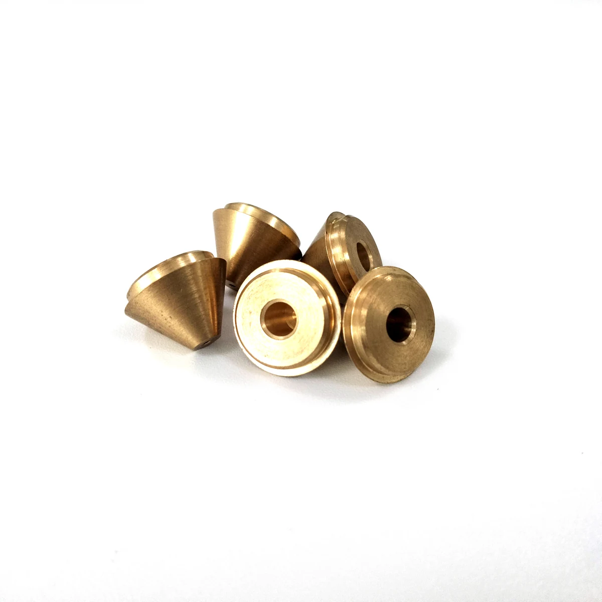
Brass nozzle forms with tapered bodies, central openings and circular shoulders. Define the bore, taper and mating interface before reviewing flow or pressure requirements.
Explore component AI-assisted studio view
An aluminum washer with a circular outline and central opening. Specify thickness, bore size and edge condition for the assembly interface.
Explore component AI-assisted studio view
Brass sleeve forms with internal bores and flanged sections. Use the mating bore, outside diameter and shoulder position to define your own version.
Explore component AI-assisted studio view
Brass ring components with a central opening and circular outer profile. Define the contact faces and dimensional relationship to the mating parts.
Explore component AI-generated engineering concept
A stepped tubular spacer concept for assemblies that need a pilot, a controlled axial distance and clearly defined contact faces.
Explore component AI-generated engineering concept
An externally threaded retaining-ring concept for optical assemblies: define the clear aperture, contact land and spanner access around the lens stack.
Explore component AI-generated engineering concept
A metallic ferrule-holder concept for a specified ceramic insert: connect bore fit, locating shoulder and assembly method before sample machining.
Explore component AI-generated engineering concept
A recessed conical-seat insert concept: define the seating profile, locating land and flow bore against the mating needle or poppet.
Explore component AI-generated engineering concept
A closed-end metal pocket concept for an inserted sensing element. Review usable bore depth, the remaining end wall and the mounting shoulder against the instrument layout.
Explore component AI-generated engineering concept
A sleeve concept for a sliding spool arrangement, bringing the internal bore, radial ports and locating surfaces into one drawing-led review.
Explore componentAI-assisted studio viewA guide-sleeve reference for moving probe assemblies. Define the bore, mounting fit and retaining grooves together so the probe has the intended clearance after installation.
Explore component
A female contact reference for industrial circular connectors. Review the mating bore and solder-cup termination together so the contact fits both the mating pin and the intended wire.
Explore component
Replaceable test probes need a stable socket fit without making servicing difficult. Review the receiving bore, retention feature and solder tail against the mating probe and fixture plate.
Explore component
A bored guide sleeve for linear-motion modules and automation fixtures. Define the shaft clearance, housing fit and guide length as an assembly, then agree the material and surface requirements.
Explore componentDRAWING-BASED PROCUREMENT
Updated
A sleeve, bushing or ring may locate on its bore, its outside diameter, a shoulder or a combination of these surfaces. Begin the supplier enquiry by naming the relationship that controls your assembly. Show the mating shaft or housing and identify which surfaces guide, retain, space or seat the component. This provides a practical way to choose a related catalogue form and turn it into a defined machining brief.
Chengshuo references in this family include brass sleeve forms, aluminum round washers and brass components with bores and seating shoulders. Their original product material identifies those materials for the specific examples. Use the relevant reference page to communicate the geometry you require, then specify your own alloy grade, dimensions and final condition. Keep alternative materials or shapes as separately identified quotation options so that purchasing can compare an agreed scope.
Define what is supplied as part of the component order. A loose sleeve, a matched set and an installed assembly can require different documentation and acceptance steps. Identify any mating parts or fixtures supplied by the buyer, and name the reviewer responsible for fit or assembly approval. The machining quotation can then describe the requested component and records while explicitly identifying any additional, separately agreed assembly work.
Locate the internal and external surfaces in the drawing datum system and state the required relationship to the locating face. Define usable contact lengths, shoulders, steps and reliefs separately from entry chamfers. Include a section where the internal form or a thin wall needs explanation. A controlled mating-part reference helps the reviewer understand which feature is intended to move, locate or remain retained during the agreed assembly process.
Call out the material grade, treatment and delivered condition before agreeing the final inspection requirements. Where a finish or coating affects a mating feature, identify the dimensions that apply after that operation and any area to be masked or protected. Define important edges and the surfaces on which handling marks matter. An inspection requirement should refer to the actual feature and condition, rather than relying on a broad precision-part description.
For a component whose assembly or clamping condition matters, describe both the condition supplied for inspection and the agreed condition used for fit review. Identify the support or fixture where it is part of the check. Ask for a proposal when access to a bore, groove or internal shoulder makes verification difficult. Agree which characteristics will be reported on the samples and keep that method with the controlled drawing.
Send Chengshuo the part drawing, relevant mating geometry, material specification, sample quantity and production scenarios. Highlight the bore, outside interface, locating face and any critical internal feature. List the requested dimensional report, material documentation and other records needed for your purchasing decision. Give the required timing and identify any unresolved interface decision so that the quotation can state its scope and assumptions clearly.
Before sample manufacture, identify the drawing revision, delivered condition and acceptance checks. Keep the measured results, sample identifiers and agreed assembly decision together. If a sample leads to a change in fit, shoulder position, material or finish, issue a controlled update and determine which checks need another review. The commercial offer confirms the selected supply boundary, documentation and timing for that specific technical package.
For production and repeat orders, protect bores, edges and locating faces using the agreed packing arrangement. Define the part and lot identity that receiving should retain after unpacking. Compare the component and its mating parts with the approved sample basis before releasing another order. A changed shaft, housing or finishing operation should be identified for review even if the sleeve or ring retains the same purchasing description.
| Feature | Define in your enquiry | Agreed reference |
|---|---|---|
| Function | Guide, locate, space, seat or retain | Defined assembly relationship |
| Mating geometry | Bore, outside surface and locating face | Controlled drawing and counterpart |
| Material and finish | Alloy, treatment and delivered condition | Agreed material or treatment record |
| Inspection state | Support, free condition or agreed fixture | Feature-specific verification method |
| Sample approval | Reported characteristics and actual mating parts | Dimensional and assembly decision |
| Repeat delivery | Protected surfaces, part and lot identity | Approved packing and revision basis |
Provide the controlled drawing, mating shaft or housing, material and quantity scenarios. Identify the locating surfaces, delivered condition and sample records required for approval.
Select a form with a comparable bore, outside profile or locating face. Use its part page to explain the geometry, then supply the complete requirements for your own version.
Your assembly design identifies whether the bore, outside surface, face or their relationship controls location. Put the required limits and datums on the controlled component drawing.
State the treatment and the dimensional condition used for acceptance. Identify affected mating surfaces, masking requirements and the material or treatment records requested with delivery.
Describe the support or clamping condition when it forms part of the agreed check. Keep the fixture or mating reference, method and acceptance requirements with the sample drawing revision.
Review the component and mating-part revisions, material, finish and fit requirements. Carry the approved sample basis, protection and lot-identification instructions into the production order.
FROM EXAMPLE TO YOUR REQUIREMENT
Use an example to explain your idea.
Your own drawing defines the final specification.
ENGINEERING KNOWLEDGE
Define shaft clearance, bushing retention and inspection condition separately, then connect size limits, geometric controls and sample checks to the assembly.
Sensor Sleeves: Review the Bore, Wall and Assembly FitPrepare a sensor-sleeve drawing around the inserted component, usable bore, wall sections and mounting interface before requesting manufacture.
Brass Nozzle Machining: Define the Passage, Connection and AcceptanceTurn a brass nozzle section drawing into a manufacturing specification: internal passages, mounting and sealing interfaces, finished surfaces and separate flow-test requirements.