
Geometry and access
Show pockets, hole patterns, slots and internal corners. Access and the relationship between faces affect the proposed route.
CNC milling
Review custom plates, blocks and housings around their pockets, hole patterns and mating faces. Mark the datums, fastener access and surfaces that need protection.
Review my cnc milling part Explore component examples
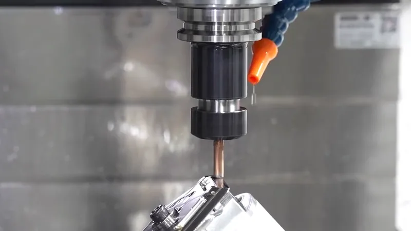
Real Chengshuo factory footage
A complete drawing package helps keep the quotation, machining route and sample checks aligned. Identify these requirements before comparing options.
Show pockets, hole patterns, slots and internal corners. Access and the relationship between faces affect the proposed route.
Identify the functional datum structure and surfaces that cannot be marked. Discuss the critical relationships between features.
Specify the checks that matter to fit and function, together with cosmetic faces, edge conditions and post-machining treatment.
REAL COMPONENT EXAMPLES

 AI-assisted studio view
An aluminum positioning block with pockets, holes and a shaped exterior. Relate the locating features to the functional datums in your drawing.
Explore component AI-assisted studio view
An aluminum fixing plate with an angled form and a central mounting opening. Define the relationship between the mounting faces and the hole centre.
Explore component AI-assisted studio view
An aluminum USB-hub enclosure with a slim profile and multiple interface openings. Port positions and the internal assembly clearance guide the drawing review.
Explore component AI-assisted studio view
A watch-case frame with a shaped outer profile and open interior. Review the assembly opening, internal recesses and cosmetic surfaces together.
Explore componentGeometry references from the Chengshuo portfolio. Each card identifies its published process; the manufacturing route for your own drawing is reviewed individually.
Aluminum / PROJECT PLANNING
Specify the exact alloy and temper. A cosmetic finish, thread fit and thin wall can introduce different requirements into the same component.
Anodizing or another treatment must be specified before final dimensions and acceptance are agreed.
Explore aluminum examplesStainless steel / PROJECT PLANNING
“Stainless steel” alone is not a complete material specification. Describe the required grade, documentation and exposure conditions so the manufacturing review starts from the same assumptions.
Corrosion performance depends on grade, finish and environment. Discuss application requirements rather than relying on appearance.
Explore stainless steel examples
Brass / PROJECT PLANNING
For connectors, sleeves and turned details, specify the brass alloy alongside the thread, sealing and finish requirements. Distinguish the visible shape from its functional acceptance criteria.
State any material-composition or regulatory requirement in your enquiry; do not infer it from a generic brass description.
Explore brass examples
Copper / PROJECT PLANNING
If a copper part has an electrical or thermal role, identify the relevant alloy and the surfaces that matter. Include any required coating or contact condition in the drawing package.
Electrical or thermal performance needs application-specific definition and verification.
Explore copper examples
Steel / PROJECT PLANNING
Specify grade and material condition, then state any heat treatment and finishing requirement. The sequence of operations should be reviewed together with the dimensions that control assembly.
Do not assume a heat treatment or hardness from a photograph. Include it as an explicit requirement.
Discuss steel requirementsYOUR DRAWING DEFINES THE ROUTE
Share it with the drawing, quantities and any inspection or compliance requirements.
Discuss the materialPlastic / PROJECT PLANNING
A polymer name, grade and environment help define how a plastic component should be reviewed. Include fit, wall features and any temperature or media exposure relevant to the application.
Polymer families are not interchangeable. The exact material and part requirements need project review.
Explore plastic examples
| Finish discussion | What it concerns | What to specify |
|---|---|---|
| As-machined | Visible cutting texture and edge condition | Define surface roughness where function requires it; specify burr removal and edge breaks. |
| Anodizing | Aluminum appearance and surface treatment | State type, color/reference sample, masking and which dimensions apply after treatment. |
| Passivation | Specified stainless-steel surface treatment | State the applicable process requirement, cleanliness and required documentation. |
| Plating | A specified deposited coating | Define coating system, thickness, substrate, masking and final functional dimensions. |
| Blasting / brushing / polishing | Specified texture or visual surface | Identify treated faces, direction or appearance standard, and features that must be protected. |
Planning options, not a blanket process or performance commitment. Availability and the treatment route are confirmed for each drawing and material.
QUALITY & ACCEPTANCE
Capability cannot be established from a generic tolerance headline. Share the geometry, material, specified limits and inspection method for your actual component.
Define my sample acceptanceExplain the mating part and the dimensions that control assembly.
Define measurement methods, sample plan and any records required.
Confirm the approved revision and review changes before a new run.
A dimensioned drawing with revision, material and finish is the starting point. A STEP model can help communicate geometry. Include quantities and the critical acceptance requirements.
No. A photo illustrates the part form. Feasibility must be reviewed against the actual geometry, material, dimension, tolerance and inspection method.
Include the requested sample quantity and the checks needed for approval. Sample scope and the intended production order are reviewed together.
The quotation confirms the reviewed scope, material, quantity, inspection requirements, price and schedule. Website examples do not constitute an offer or an accepted production order.
FROM EXAMPLE TO YOUR REQUIREMENT
Use an example to explain your idea.
Your own drawing defines the final specification.
FROM PROCESS TO REQUIREMENTS
See the workshop context, compare relevant component geometries and define how your samples will be checked.
Send the current drawing with quantities and critical requirements. The review is the starting point for agreeing scope, quotation and sample approval.
Request a drawing reviewSEE THE PROCESS IN MOTION
Explore Chengshuo’s published machining and workshop films. The project review connects your drawing to a proposed manufacturing and inspection route.
Machine-interior views show the spindle, cutting tool and held components.
How will tool access, clamping references and secondary features be defined?
Pocketed positioning blocksReview my part with this process A close look at material removal, followed by digital process planning.
Which diameters, shoulders and thread features control your assembly?
Shafts, pins & mating fitsReview my part with this process Every component starts with a specific requirement. We review its material, geometry and inspection needs before confirming the machining route.
Explore process filmsBefore releasing a milled part
Review the features that determine whether the part can be machined, assembled and inspected as specified.
Compare the pocket corner with its insert before approving a radius or relief.
Distinguish face flatness from parallelism and state the inspection restraint.
Identify the edges to break, the surfaces to protect and the acceptance method.