Skip to content
CHENGSHUOPRECISION
EN
Request a drawing review

SMALL FEATURES • FIT • HANDLING

Machined interfaces for sensor and instrument assemblies

Source the metal parts around your sensing element and assembly. We manufacture to agreed drawings and inspection requirements; the complete device defines sensing and sealing performance.

Explore 4 relevant cases
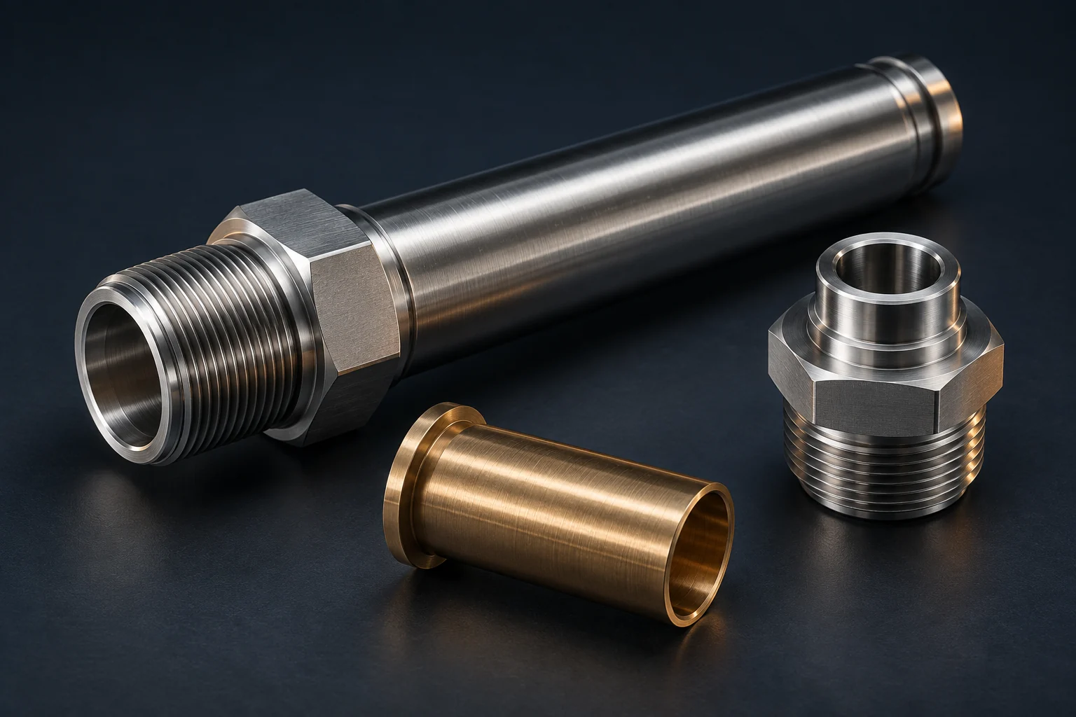
Illustrative sensor tube housings, threaded process connection bases and thin-wall guide sleeves
Illustrative component forms · manufacturing review required

FOR SENSOR AND INSTRUMENT OEMS

Machine the interface. Protect the fit.

Source the machined sleeve, body or shaft around your assembly. We establish the component requirements with you; sensing and sealing performance need assembly validation.

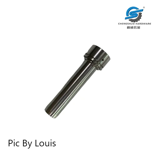
Sensor base sleeve, official Chengshuo product photograph 1
Company product photographOpen source image

01Sensor base sleeve

Insert clearance and a locating shoulder

A long sleeve leaves room for the internal insert while locating at the mounting shoulder; the manufacturing route follows the drawing.

Before quotation and sampling

Supply insert envelope, insertion depth and sealing interfaces; agree bore, wall and shoulder records. Sensing performance stays at assembly level.

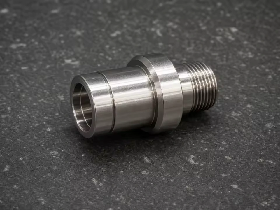
Miniature connector body — Huantong listing visual
Store display visualOpen source image

02Miniature connector body

Threads around a hollow body

Bore access, thread engagement and coating allowance need to work together when a connector body joins a housing.

Before quotation and sampling

Send mating threads and insert geometry; agree final thread gauging and seating dimensions. Application suitability remains drawing-specific.

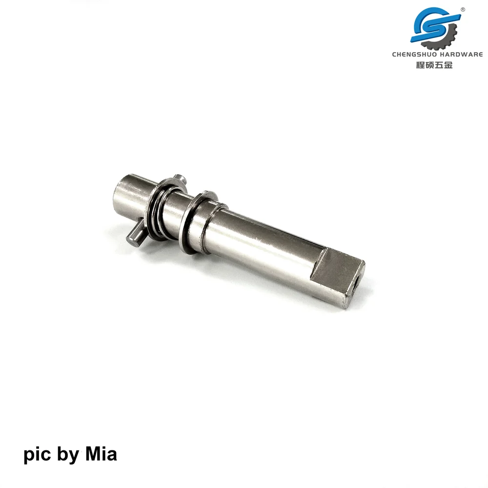
Stainless steel main shaft, official Chengshuo product photograph 1
Company product photographOpen source image

03Stainless steel main shaft

Journals with shoulder references

A stepped shaft needs clear datum relationships so diameter fits, shoulder positions and grooves refer to the intended assembly.

Before quotation and sampling

Mark locating surfaces and mating parts; agree measured characteristics and revision-linked sample records before repeat production.

YOUR PROJECT. YOUR PRIORITIES.

Make the purchasing
decision specific.

Align engineering, sourcing and quality around a clear part definition before the quotation and sample review.

01

Define the function of each small feature

Separate locating diameters, guide bores, shoulders and clearance features. Include insertion direction and edge requirements, especially where a small burr or transition can complicate assembly.

02

Specify material by requirement

State the exact alloy, condition and finish on the drawing. If an interface has an electrical, magnetic, optical or chemical requirement, supply the applicable specification and acceptance test for a separate capability review.

03

Plan inspection and handling together

Agree how critical small features will be measured and which sample checks need mating parts. Specify separation, protection and identification during packing where surface damage or mixed revisions could affect your build.

YOUR NEXT ORDER / EVIDENCE & REQUIREMENTS

Connect small-part approval to the order package.

Use a focused pin inspection plan to define the sample, and a recorded pin delivery to examine the commercial handover.

Explore the part inspection plan

Relevant order handovers

Pin order handoverDelivery recorded 29 Jun 2026

Selected for the purchasing question. The customers’ actual industries are not disclosed.

FROM THE CHENGSHUO PORTFOLIO / 4 SELECTED REFERENCES

Inspect the actual
component references.

Explore more reference geometries
Brass conductive pillars — AI-assisted studio presentation based on the original Chengshuo photographView product case AI-assisted studio view
BrassElectronics OEMs

Brass contact pillars

Stepped brass components with locating and contact regions. Define mechanical fit, surface condition and any required electrical tests separately.

REVIEW FOCUSStepped locating diameters
Explore the case

NEW / ENGINEERING CONCEPT COLLECTION

More forms for your application.

Purposeful component forms for automation, sensors and fluid equipment. Explore the geometry and buying decisions, then develop your own drawing-led brief.

Optical lens retaining ring — AI-generated engineering conceptcs-product-064

AI-generated engineering concept

Sensors & instrumentation

Optical lens retaining ring

A retaining ring may thread into the barrel yet contact the lens incorrectly or obstruct the intended aperture.

Key geometry & review priorities

Fine external thread · Opposed spanner slots · Annular retaining contact land

  • Clear aperture
  • Contact land
  • External thread
  • Spanner slots

Feasibility and acceptance require your drawing.

Discuss this geometry
Bulkhead connector shell — AI-generated engineering conceptcs-product-065

AI-generated engineering concept

Sensors & instrumentation

Bulkhead connector shell

The shell can meet its outside dimensions while the panel, locking hardware and insert do not align.

Key geometry & review priorities

Panel-mount threaded neck · Wrench shoulder and orientation flat · Internal insert locating seat

  • Panel seating
  • Insert location
  • Orientation
  • Finished connection

Feasibility and acceptance require your drawing.

Discuss this geometry
Coaxial center contact — AI-generated engineering conceptcs-product-066

AI-generated engineering concept

Sensors & instrumentation

Coaxial center contact

Plating, termination geometry and insulator fit can change an otherwise acceptable turned-contact interface.

Key geometry & review priorities

Solid turned mating tip · Concentric insulator locating shoulder · Rear termination cup

  • Mating tip
  • Insulator seat
  • Termination cup
  • Coating allowance

Feasibility and acceptance require your drawing.

Discuss this geometry
Ceramic ferrule holder — AI-generated engineering conceptcs-product-067

AI-generated engineering concept

Sensors & instrumentation

Ceramic ferrule holder

A holder can pass a bore check yet locate the ferrule at the wrong depth or stress it during assembly.

Key geometry & review priorities

Ferrule receiving bore · Axial locating shoulder · External mounting pilot

  • Receiving bore
  • Axial stop
  • Mounting reference
  • Assembly cleanliness

Feasibility and acceptance require your drawing.

Discuss this geometry
Blind-bore sensor pocket — AI-generated engineering conceptcs-product-055

AI-generated engineering concept

Sensors & instrumentation

Blind-bore sensor pocket

Overall length and drilled depth can look acceptable while the sensor has the wrong insertion space or end contact.

Key geometry & review priorities

Blind axial sensor bore · Closed sensing-end wall · Mounting shoulder

  • Usable bore depth
  • Remaining wall
  • Mounting position
  • Validation ownership

Feasibility and acceptance require your drawing.

Discuss this geometry
Threaded sensor end cap — AI-generated engineering conceptcs-product-056

AI-generated engineering concept

Sensors & instrumentation

Threaded sensor end cap

A cap can screw into place while trapping an internal component or compressing the seal against the wrong surface.

Key geometry & review priorities

Closed cup-shaped end · External closure thread · Internal clearance pocket

  • Thread-to-seat relationship
  • Internal clearance
  • Seal contact
  • Cosmetic surfaces

Feasibility and acceptance require your drawing.

Discuss this geometry
Cable-entry compression body — AI-generated engineering conceptcs-product-057

AI-generated engineering concept

Sensors & instrumentation

Cable-entry compression body

The mounting thread can be correct while the cable or sealing insert is mismatched to the internal passage.

Key geometry & review priorities

Hexagonal wrench flats · Threaded mounting section · Stepped cable passage

  • Enclosure mount
  • Cable passage
  • Seal support
  • Wrench access

Feasibility and acceptance require your drawing.

Discuss this geometry

AI-generated geometry studies, not photographed production or completed customer projects. Each concept includes a manufacturing review brief; specifications are agreed from your drawing.

Explore all new component references

THE HANDOVER TO CHENGSHUO

Send the information
that moves the review.

  • Current model and drawing with critical feature callouts
  • Exact material and finishing requirements
  • Assembly method, mating features and sample test scope
  • Handling, cleanliness and packing requirements
Request a drawing review

What if the part has an electrical or sensing function?

Include that specification and the required test procedure with the mechanical drawing. Machining geometry and functional device validation need clearly agreed scopes and acceptance owners.

Product examples help define the conversation. Suitability is assessed against your component specification.


Full drawing & RFQ checklist

EXPLORE ANOTHER BUYER PATHWAY

From drawing to project review.

Read the film transcript

Start with your drawing. Define material and finish. Identify critical features. Align samples and production quantities. Request a project review. Illustrative renders and Chengshuo component photography; this is a project overview, not machining footage.

Discuss your drawing

CHENGSHUO / PROCESS FILMS

Process film

Silent process film. Workshop footage is process context; it is not a record for the reference component.

View original