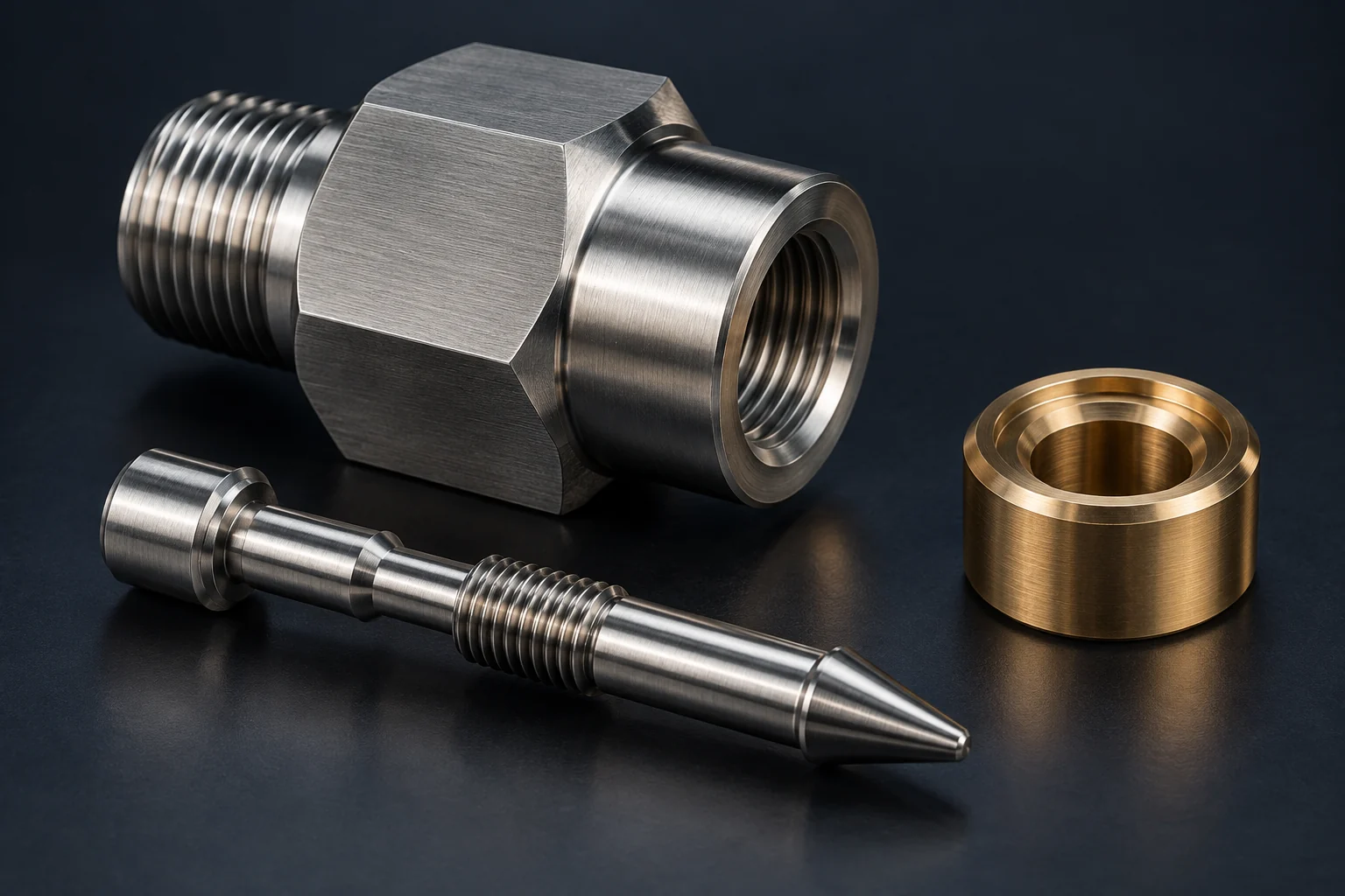
01 / COMPONENT FORM
Hex through-bore adapters
Join the assembly through a threaded connection and an internal passage.
Thread standard, wrench access, through-bore edges and the actual sealing interface.
THREADS • BORES • SEAL INTERFACES
Bring the two mating connections, internal passage and seal interface into the same drawing review. Compare photographed connectors and bored parts, then state the thread checks, internal-edge requirements and any separate functional tests your assembly needs.
Explore 4 relevant cases
YOUR COMPONENT SELECTION
Include section views, the intended sealing method and internal-edge requirements. Specify any pressure, leakage or cleanliness test for capability review.
01 / COMPONENT FORM
Join the assembly through a threaded connection and an internal passage.
Thread standard, wrench access, through-bore edges and the actual sealing interface.
02 / COMPONENT FORM
Connect a moving stem to the specified guiding and contact surfaces.
Tip geometry, stem datums, mating guide and the required functional test scope.
03 / COMPONENT FORM
Provide the defined bore and contact surface for the mating valve element.
Seat profile, contact finish, bore relationship, material and assembly method.
Review the component machining route
Plan the sample acceptance records
For more than one component, bring the assembly interfaces into one review. Include a drawing and quantities for each part.
Photographed references illustrate related geometry. They do not establish that the illustrated forms have been supplied or qualified for your application.
YOUR PROJECT. YOUR PRIORITIES.
Align engineering, sourcing and quality around a clear part definition before the quotation and sample review.
Specify thread standard, size, pitch and class together with usable engagement. Identify the actual seal and the surfaces it contacts; dimensional thread acceptance and assembled sealing performance are different checks.
Show cross holes, bore intersections, end edges and inaccessible regions in section views or a model. Name the features requiring deburring, and define cleanliness requirements with an agreed inspection method.
If a pressure, leakage or media-compatibility test is needed, include its procedure, conditions and acceptance criteria. Confirm the test scope and supplier capability before including it in the commercial agreement.
YOUR NEXT ORDER / EVIDENCE & REQUIREMENTS
Map the turned body, slot and functional edges on your drawing. For a multi-item order, agree the requirements and receiving documents by line.
Explore the part inspection planRelevant order handovers
Mixed-component orderDelivery recorded 21 Jul 2026Selected for the purchasing question. The customers’ actual industries are not disclosed.
FROM THE CHENGSHUO PORTFOLIO / 4 SELECTED REFERENCES

Bore, side access and textured grip features. Establish the connection geometry and the requirements at each functional interface.

Bored bodies with external grooves and stepped ends. Connect the internal fit to the features that retain and locate the joint.

Thread engagement, outer recesses and a seating face. Define the mating thread, tool access and final finishing condition.

Turned bodies with a secondary milled slot. Review the slot location, contact edges and relationship to the turned axis.
NEW / ENGINEERING CONCEPT COLLECTION
Purposeful component forms for automation, sensors and fluid equipment. Explore the geometry and buying decisions, then develop your own drawing-led brief.

AI-generated engineering concept
Fluid control & equipment
The same tip length can produce a different relationship to the seat if taper definition and axial travel are unclear.
Controlled metering taper · Guided stem journal · Adjustment thread and shoulder
Feasibility and acceptance require your drawing.

AI-generated engineering concept
Fluid control & equipment
A fitting can assemble mechanically while an uncontrolled burr or damaged sealing face compromises the intended flow path.
Central bolt-eye passage · Parallel annular sealing faces · Threaded side connection
Feasibility and acceptance require your drawing.

AI-generated engineering concept
Fluid control & equipment
A nominally matching thread does not establish that the internal shoulder, gland and seal stack are compatible.
Internal connection thread · Annular gland-retaining shoulder · Hexagonal wrench interface
Feasibility and acceptance require your drawing.

AI-generated engineering concept
Fluid control & equipment
A visible cone does not define the contact band, installed position or leakage behavior of the valve.
Recessed conical seating surface · Concentric flow passage · External locating land and flange
Feasibility and acceptance require your drawing.

AI-generated engineering concept
Fluid control & equipment
Acceptable hole sizes do not establish the intended overlap, sliding behaviour or internal edge condition.
Axial spool bore · Radial port pattern · Outer locating shoulders
Feasibility and acceptance require your drawing.

AI-generated engineering concept
Fluid control & equipment
A hose-tail diameter alone does not define tube fit, assembly damage or retention inside the device.
Rounded hose-barb profile · Axial through passage · Shoulder and retaining groove
Feasibility and acceptance require your drawing.
AI-generated geometry studies, not photographed production or completed customer projects. Each concept includes a manufacturing review brief; specifications are agreed from your drawing.
Explore all new component referencesTHE HANDOVER TO CHENGSHUO
No. Identify the intended sealing system and its contact surfaces separately. Provide the mating interface and any required functional test so the quotation covers the correct scope.
Product examples help define the conversation. Suitability is assessed against your component specification.

Full drawing & RFQ checklistEXPLORE ANOTHER BUYER PATHWAY
ENGINEERING KNOWLEDGE
Turn a brass nozzle section drawing into a manufacturing specification: internal passages, mounting and sealing interfaces, finished surfaces and separate flow-test requirements.
Compare Machining Quotes with a Line-by-Line Scope WorksheetNormalize sample, first-release and repeat-order costs while checking inspection, finishing, packing and delivery assumptions before choosing a machining supplier.