

 AI-assisted studio view
cs-product-009
Stainless steel mechanical joint
A stainless steel joint with a cylindrical body, central bore and external grooves. Identify the contact surfaces and fit requirements for your assembly.
Explore component
Studio image: AI-assisted presentation. Select an original photograph to review the source.
Threaded components / cs-product-007
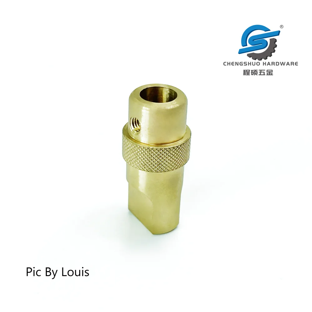
A brass joint reference with an open central bore, a textured outer collar and a side opening. Start the supplier enquiry with the surfaces that locate, connect and contact the mating parts, then agree the material, delivered condition and inspection requirements.
Send your drawing, quantity and mating-part requirements for a project-specific quotation.
Download review brief
THE PRODUCT CASE / YOUR BUYING DECISION
A valve-joint body brings installation and internal passage requirements together. Use this brass reference to clarify the central bore, side opening and textured collar, then define the connection details and cleanliness checks needed for your equipment.
Explore this product caseBEFORE YOU RELEASE THE DRAWING
Use these guides to define the records and checks your component needs.
Made-to-drawing procurement
Updated
A joint used in a valve-related assembly should be described through its actual connections. Identify what enters the central bore, what contacts the end faces and how the outside features are used during installation. State the mating-component references needed to understand those relationships. This gives the supplier a component-level requirement against which to review your drawing.
The Chengshuo product reference shows a brass body with a visible opening and textured collar. The original views provide a way to discuss the shape and connection ends. Select the relevant form as a reference, then send the dimensions, revision and units for your own part. Include a model where it helps explain an internal passage or a stepped interface.
Keep the supply boundary explicit. A loose joint component, a matched set and a complete installed assembly involve different purchasing and acceptance decisions. List any additional seals, fasteners or counterpart items separately. If you need assembly work or a functional check in addition to the component, describe that scope and the person responsible for approving the result.
Assign a drawing datum to the surfaces that locate the joint in the assembly. Define the relationship between the central bore, the end interfaces and any side opening that matters to installation. Distinguish a locating diameter from a passage that only provides clearance. Add sectional views where the internal profile or the transition between features would otherwise be unclear.
Describe each connection end independently. Where a thread is required, specify its system, size and acceptance requirement. Where a sealing or contact face is part of the design, identify its geometry and the condition in which it is inspected. Put important entry edges, reliefs or tool-access requirements on the controlled drawing rather than relying on a general fitting description.
Explain the intended use of the textured outer collar where it affects the enquiry. A hand-contact area, an assembly-tool interface and a cosmetic feature can have different acceptance requirements. Mark the areas on which handling or appearance matters, and state any reference sample used for comparison. Keep those requirements separate from the dimensions that control the mating fit.
Name the brass designation and material standard required for your component. List the material records you need and any separately requested finishing operation. If a treatment affects the bore, threads or contact faces, state the final condition used for acceptance. Alternatives should be identified as separate options with an agreed approval route, so the quotation follows a consistent technical basis.
| Feature | Enquiry and acceptance |
|---|---|
| Bore | Locating or clearance function Record: Controlled geometry and datum |
| Mating ends | Connection type and counterpart Record: Interface acceptance criteria |
| Side opening | Position and intended role Record: Drawing or assembly reference |
| Collar | Handling, tooling or appearance needs Record: Agreed surface acceptance |
| Material | Brass designation and final condition Record: Requested material records |
| Sample | Reported features and separate functional tests Record: Documented approval basis |
Identify the features to be reported on samples and the method or reference needed to check them. If a mating component, gauge or fixture is supplied by the buyer, describe its purpose and availability. Separate dimensional inspection of the joint from a test of a complete valve, fluid path or installed system. Any requested functional test should include the actual procedure, conditions and acceptance rule.
Send sample and first-order quantities, destination and required timing with the drawing. Keep the material specification, critical features, finishing and documentation requirements together in the enquiry. The quotation can then state the accepted machining and supply scope. If sample review leads to a change in a mating end or bore relationship, issue a controlled revision and identify the checks to repeat.
For delivery and repeat orders, agree protection for bore entries, connection ends and important contact surfaces. Define the part, revision and batch identification that connects the shipment to the approved sample basis. Review changes in the mating hardware or assembly process before reordering. The enquiry link retains this brass joint reference while you add the controlled details for your own component.
The reference shows an open central bore, a textured outer collar and a side opening. Your drawing defines the required mating details.
Specify the actual connection standard, dimensions and sealing requirements in the drawing and enquiry so they can be reviewed for the project.
Provide the required designation and material standard, together with any permitted alternatives and requested material records.
State whether it serves handling, a tool interface or an appearance requirement, and identify the relevant acceptance basis.
Describe the assembly, procedure, conditions and acceptance rule separately from component measurements. The test scope is agreed for the actual project.
Retain the approved drawing revision, sample decision, inspection and material records. Review any changes to mating parts, finish or assembly before reordering.
AI-assisted studio viewA stainless steel joint with a cylindrical body, central bore and external grooves. Identify the contact surfaces and fit requirements for your assembly.
Explore component AI-assisted studio view
An internally threaded lock nut with repeated outer recesses. Specify the thread standard, mating part and tool-access geometry for your version.
Explore component AI-assisted studio view
An extended bolt with a long threaded section and a smooth shank. Define the thread, engagement length and head-access requirements for a similar fastener.
Explore componentFROM EXAMPLE TO YOUR REQUIREMENT
Use an example to explain your idea.
Your own drawing defines the final specification.
FROM COMPONENT TO PROJECT
Start with the component geometry, then check what the drawing, sample and order records need to establish for your own part.
Send the current drawing with quantities and critical requirements. The review is the starting point for agreeing scope, quotation and sample approval.
Request a drawing review