 5 min read

Does a brass cone body establish a cone-shaped spray?
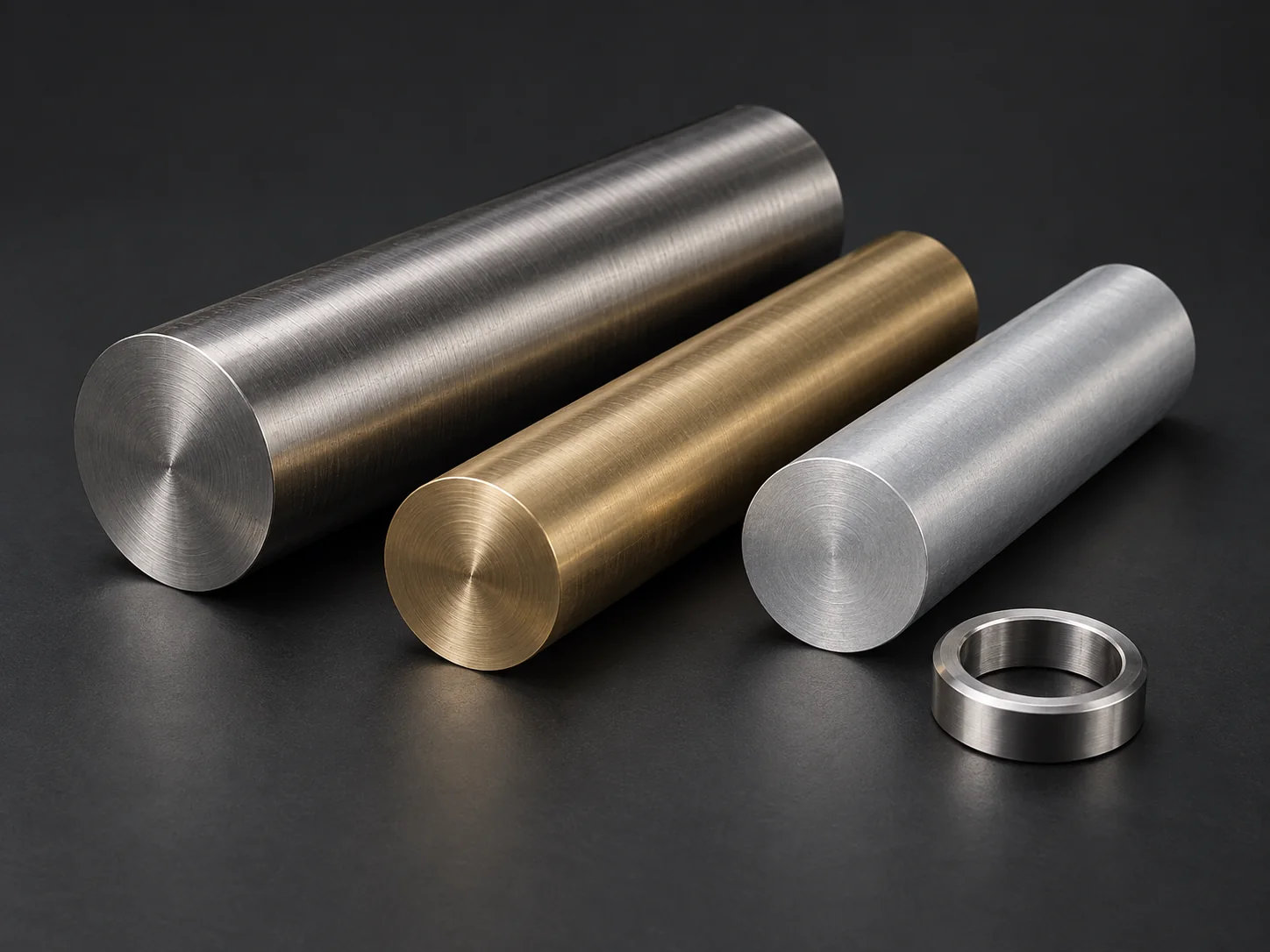
A brass nozzle is a component made from a specified brass alloy that directs fluid through a passage to an outlet. In a spray assembly, the outlet and internal features help shape the discharge. The term brass identifies the material family; it does not, by itself, specify a spray pattern, flow rate or pressure rating.
A machined nozzle body may work with a separate insert or swirl element. Lechler identifies outlet geometry, internal geometry, fluid properties and the way fluid enters as factors in spray formation. An external cone is therefore a description of the metal shape, not proof of a cone-shaped spray. Establish which part of the complete nozzle is being purchased.
What must a nozzle passage drawing show?
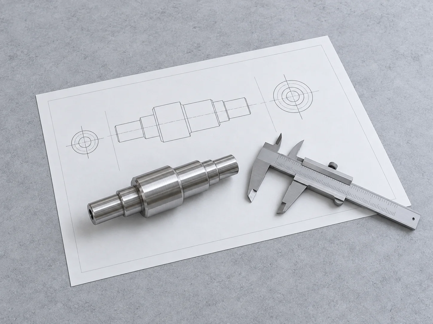
A useful section drawing follows the route from inlet to outlet and gives each diameter, transition and depth a reference. Distinguish the controlled straight length from the total hole depth and show the required bottom or transition profile. For a separate insert, identify its seat and the interface that fixes its position.
- Inlet and passage: state diameters, usable lengths, steps and intersections; identify blind and through features.
- Outlet: define the opening, its axis or position and the permitted edge profile; do not leave the discharge edge to a general chamfer note.
- Internal elements: show insert seats or other features and state who supplies the separate components.
- Wall and access: show the remaining wall near threads and cross passages, plus the direction from which each feature can be machined.
- Verification: identify the section, bore or outlet dimensions that require a recorded result and how the feature can be accessed.
Does the thread designation define the seal?
A thread can retain the nozzle while a shoulder, taper or separate seal closes the fluid path. Show the intended sealing arrangement instead of assuming the thread designation explains it. Specify the thread standard, size, pitch and required engagement, and identify the seating surface and mating component.
For a blind threaded connection, distinguish usable thread length from drilled depth; the blind-thread depth guide explains the separate drawing inputs. Include wrench flats or other installation features and any orientation requirement. If the mating part determines where the nozzle stops, provide that interface section. These details connect the mounting interface and outlet to the same controlled part definition.
Which alloy and finished condition should be specified?
Specify the exact brass grade and condition with the material documents required for the order. State the medium and operating environment for the responsible engineer's compatibility assessment. Colour does not identify an alloy or establish its suitability for a particular liquid, temperature or exposure.
Mark sealing faces, insert seats and outlet edges with their required final condition. Where treatment is specified, identify masked surfaces and dimensions that apply after treatment. Separate removal of burrs and loose machining debris from a quantified cleanliness requirement. Define the internal locations to inspect; a polished exterior cannot document an inaccessible passage.
Does the outlet diameter establish flow acceptance?
Small openings, long passages and internal steps need a route that can both create and verify the feature. Cross passages also introduce hidden intersections: Sandvik Coromant identifies chip evacuation and internal deburring as challenges in cross-hole drilling. Supply those details early so tooling, sequencing and inspection access are part of the quotation rather than unresolved assumptions.
No. An outlet-diameter result records one geometric characteristic; it does not document a flow or spray test. Lechler explains that flow and spray angle depend on pressure and liquid viscosity, with differential pressure relevant when there is backpressure. Define the required operating conditions and acceptance limits with the responsible engineer instead of adopting a catalogue curve for a similar-looking part. Use the inspection-requirements guide to keep the component characteristics and any separate functional-test records distinct.
What must a custom brass-nozzle quotation cover?
The machining brief should contain the controlled drawing and revision, alloy, surface requirements, quantities and inspection records. If a functional test is required, define it separately: test medium, temperature, inlet and outlet conditions, assembly configuration, measured output and acceptance limits. For spray coverage, also specify observation distance and orientation.
Ask the quotation to identify each agreed deliverable: the machined body and dimensional records, any supplied insert or assembly, and any separately specified functional-test report. State who supplies inserts and fixtures, performs assembly and testing, and reviews the results. If a test or its responsible party is unresolved, flag it as an open RFQ decision rather than treating a machining quotation as test approval. Use Chengshuo's brass-nozzle and connection examples to discuss geometry, then specify the flow-test record and operating rating required for your assembly.
FROM THE GUIDE TO YOUR PART
Put the checks into context.


References & further reading
- Lechler — Geometry and fluid factors in spray formation

- Lechler — Flow, pressure and spray functions
- Sandvik Coromant — Cross-hole drilling challenges
General planning guidance. Feasibility and acceptance criteria are confirmed against your drawing.