 4 min read
The corner is part of the assembly clearance
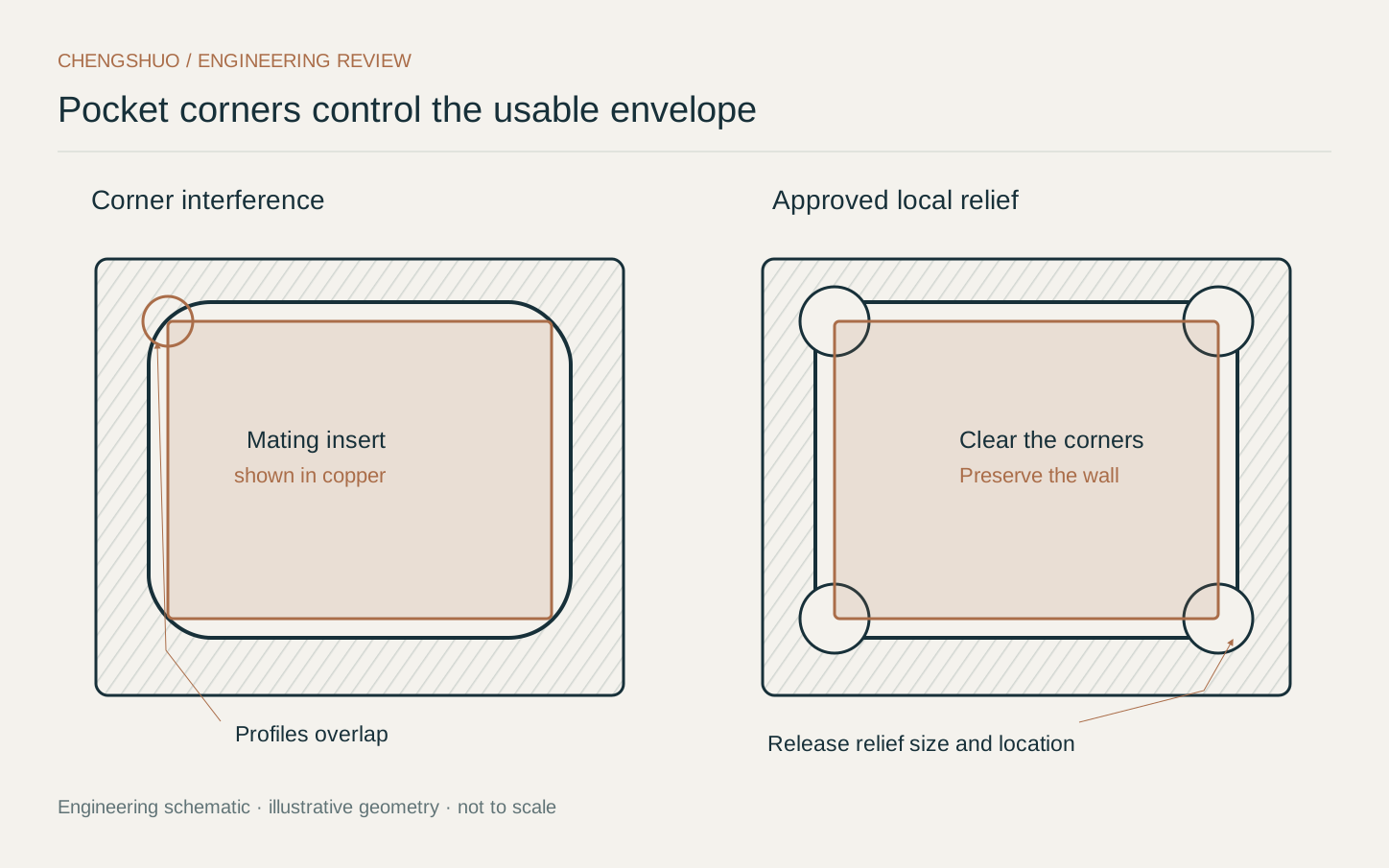
A pocket can meet its width and length limits while a square-edged mating component still cannot sit inside it. The interference may be confined to the four internal corners. An end mill leaves a radius where vertical pocket walls meet, so the usable envelope differs from a sharp-cornered CAD rectangle. Before requesting a quote for an enclosure or locating block, compare the permitted pocket profile with the actual insert profile. Include corner treatments on both parts, not just their overall dimensions.
Review radius together with pocket depth
A smaller internal radius restricts the cutter size that can reach the corner. Pocket depth then affects the required tool reach and the stiffness available during cutting. Protolabs describes this radius-and-access trade-off in its machining design guidance. Give the supplier the largest radius that the assembly can genuinely accept, with a tolerance or maximum where appropriate. Do not copy a nominal cutter radius into the drawing as a guaranteed finished result. The machining route must also account for tool motion and the required wall finish.
Choose an approved way to clear the mating corner
There are several design routes: round or chamfer the insert, enlarge the permitted pocket corner, or add a defined local corner relief. A relief can provide clearance for a square insert, but it removes material outside the nominal pocket envelope. Check adjacent holes, sealing lands, wall thickness and cosmetic surfaces before approving it. If none of these changes is acceptable, discuss an alternative manufacturing route. A supplier should not add an unshown relief simply because it makes the pocket easier to machine.
Illustrative review: width clearance does not settle corner fit
Imagine a hypothetical rectangular insert with small external corner radii placed in a pocket with larger internal radii. The width and length clearance may look adequate in separate dimension chains, yet the corner profiles can overlap. Compare the two tolerance envelopes in the assembled position, including allowed offset and orientation. If a local relief is selected, release its size and location on the controlled drawing. This example describes a geometric review; it is not evidence that a particular product has passed a fit or load test.
Inspect the contour that the insert actually uses
Separate vertical corner radii from the wall-to-floor fillet: they affect different portions of the mating component. Agree how the pocket profile, depth and floor seating will be inspected, then define any additional assembly trial using the nominated insert. A fit trial alone does not record every feature dimension, while separate width and depth readings may miss a corner obstruction. For a Chengshuo milling review, include the insert model or controlled drawing alongside the pocket drawing and identify:
- Pocket width, length, depth and functional locating surfaces.
- Vertical corner radius limits and wall-to-floor fillet limits.
- Mating insert corner profile and allowable assembly clearance.
- Permitted relief geometry and areas where material must remain.
- Contour inspection, floor seating and sample acceptance requirements.
FROM THE GUIDE TO YOUR PART
Put the checks into context.


References & further reading
- Protolabs — Mastering complex features: internal radii and corner relief

- Protolabs Network — Designing CNC parts: cavities and internal edges
General planning guidance. Feasibility and acceptance criteria are confirmed against your drawing.