 6 min read
Give the different hole depths distinct callouts
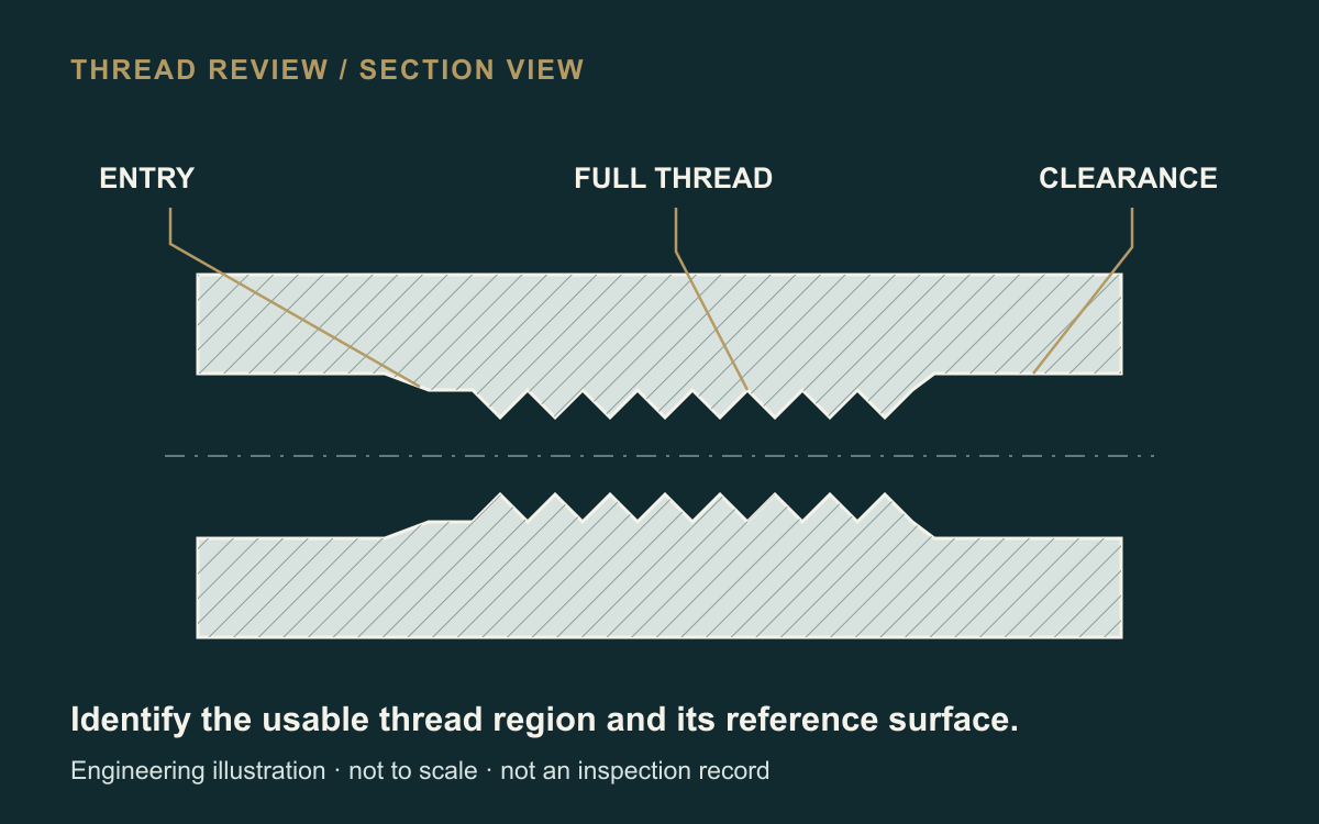
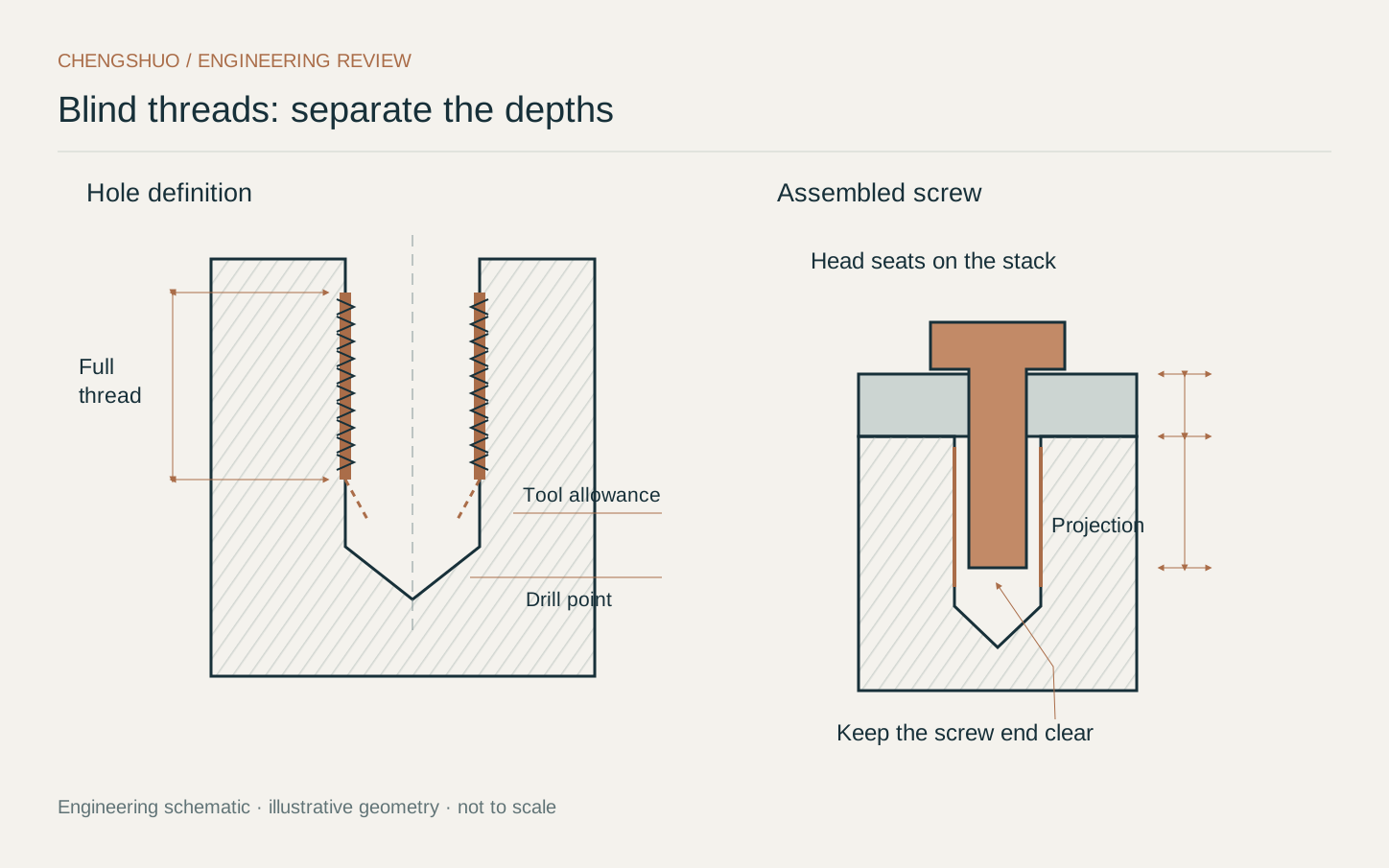
Identify the required complete internal thread, the cylindrical drilled region and the permitted overall cavity depth. Show the reference face from which each depth is defined. Distinguish the drill-point region, entry chamfer, relief and incomplete threads on a section view. A complete thread callout and a clear hole envelope give manufacturing and inspection separate features that they can review against the same drawing.
Begin with the joint’s required usable engagement, selected by the design owner. Then review the remaining space with the manufacturing contact. Preserve the outside wall, nearby passage or opposite surface that limits the hole envelope. If the proposed process requires more room, document the requested change and its design decision before sampling. Keep the original and revised views together in the controlled quotation record.
Review screw projection at both stack conditions
Identify the screw length definition and tolerance, head seating condition, washers, counterbores and clamped parts. Determine how far the screw projects into the receiving component for the relevant tolerance conditions. Have the design owner check the required minimum engagement and the available clearance at the screw end. Include the entry and incomplete-thread regions when identifying the usable internal thread.
Record the complete assembly definition rather than checking a loose screw against one nominal hole depth. A change in washer thickness, counterbore depth or clamped-part thickness can change both engagement and clearance. Use the current assembled stack for approval and preserve its revision with the hole drawing. The required load capacity and numerical engagement belong to the project design calculation and approved specification.
Ask for a process proposal within the approved envelope
Discuss tapping, forming or thread milling with the manufacturing reviewer as appropriate to the material and geometry. SFS’s thread-generation guide distinguishes these processes and explains the significance of tap lead and chip evacuation for blind holes. Sandvik’s CoroTap 300 range is specifically described for blind-hole tapping. These references support a process discussion; the selected tool and actual allowance must fit the part being reviewed.
Ask the supplier to identify the proposed thread process, available bottom space and any requested drawing change. Keep the required complete thread length separate from tool travel. Include chip removal and access where the hole intersects another feature or leaves a thin wall. Review a special bottom geometry or relief explicitly so quotation assumptions are resolved before the machining route is released.
Inspect the finished thread against named characteristics
State the thread system, size, pitch, tolerance class and required finished condition. Identify the gauge or other agreed method for the characteristics being checked. Add a separately defined check for usable thread depth and the permitted hole envelope, with the inspection specialist selecting an appropriate method and reference. Connect each result to the drawing characteristic and part identity.
Review the effect of coating, treatment and entry finishing on final acceptance. Specify whether the reported result applies after the final operation and how the thread is protected afterward. If a depth indication depends on the gauge geometry or inspection setup, document that basis in the instruction. Receiving should be able to relate the reported result to the same complete-thread requirement used during sample approval.
Close the order with a drawing and inspection worksheet
Use the worksheet to gather the drawing decisions, process proposal and report requirements in one place. Ask the buyer, design owner, manufacturing contact and quality reviewer to identify any open item. Resolve an unclear depth reference or thread condition through the responsible drawing decision. Keep an approved change attached to the quotation and sample instruction rather than leaving it in an informal verbal handover.
Consider a representative flange with a blind mounting hole beside a sealed passage. The drawing needs the usable thread for the screw, the cavity boundary that protects the passage and the assembly clearance at the screw end. Review all three before agreeing the process route. Select sample and lot records that correspond to these characteristics. Project dimensions come from the controlled design rather than a universal depth multiplier.
| Decision | Agree before ordering | Retain with the order |
|---|---|---|
| Thread definition | System, size, pitch, class and final condition | Controlled drawing revision |
| Usable length | Complete thread and reference face | Named depth characteristic |
| Cavity envelope | Drilled region, point and limiting wall | Section and permitted boundary |
| Mating stack | Screw projection and stack tolerances | Approved assembly definition |
| Inspection | Thread, usable-depth and envelope methods | Traceable sample report |
| Repeat release | Screw, finish or process changes | Referenced order/sample basis |
Preserve the approved stack for repeat ordering
Send Chengshuo the current part drawing, screw and mating-stack definitions, material, final finish and quantities. Mark the complete-thread depth, depth reference and limiting wall or nearby feature. State the required dimensional and sample records. Ask for a separate proposal where the manufacturing route needs a change. This gives the supplier a specific review package and lets the buyer compare equivalent order scopes.
Before a repeat order, review screw length, clamped thickness, washers, counterbores and thread or treatment revisions against the approved basis. Check that any manufacturing change preserves the complete thread and the allowed cavity envelope. Retain the sample approval, inspection instruction and lot identification together. At receiving, review deviations through the agreed quality process and keep their scope tied to the affected order.
Questions before your drawing review
Is drilled-hole depth the same as usable thread depth?
Identify complete internal thread, drilled region and overall cavity depth as separate features, all referenced to a clear drawing face.
Who selects the required thread engagement?
The design owner selects it from the actual joint, materials and load requirements. Manufacturing then reviews how to produce that requirement within the allowed hole envelope.
What should be checked for screw bottoming?
Review screw projection through the assembled stack at the relevant tolerance conditions, including seating features, washers, entry geometry and incomplete-thread regions.
Can a different threading process use less bottom space?
Request a specific process proposal and review its tool, material and geometry requirements. Approve any change while retaining the required complete thread and cavity boundary.
How should thread-depth inspection be specified?
Identify the usable-thread characteristic, reference face and agreed measurement method. Document the gauge or setup basis and retain results linked to the part and drawing revision.
What should accompany the machining enquiry?
Provide the part and assembled-stack drawings, screw specification, material, finish, quantities, limiting features and requested sample or lot inspection records.
Prepare the drawing review
Technical references: SFS — internal thread manufacturing processes, Sandvik Coromant — blind-hole tapping tools.