 7 min read
Begin with the supported optic and the complete stack
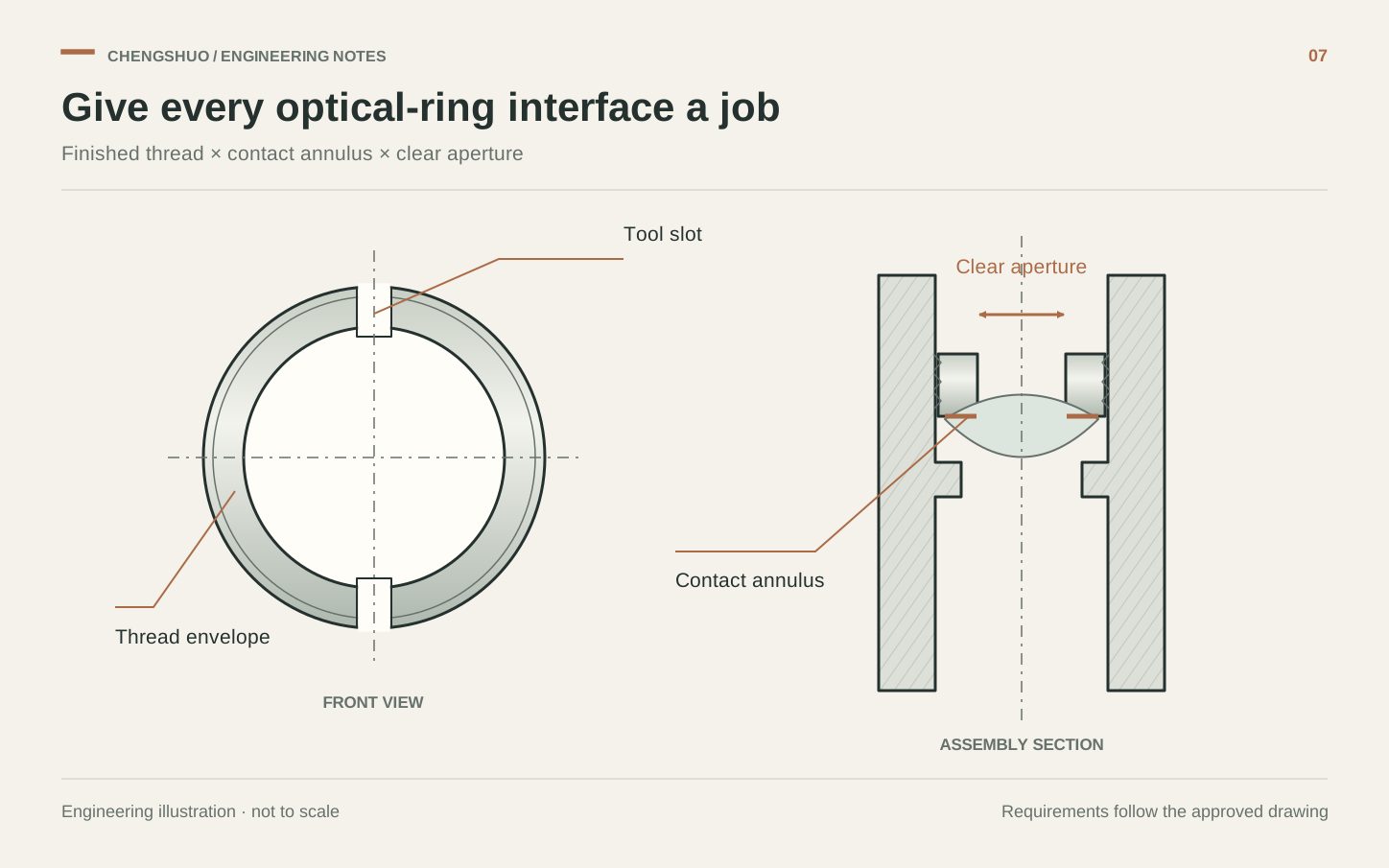
Provide a section showing the lens, ring, barrel shoulder and any spacer or compliant element. Identify which mechanical surface the retainer is intended to contact and which areas must remain clear. Show the relevant lens envelope supplied by the optical designer, including the edge or bevel where it affects contact. The ring maker needs this interface information even when the order covers the machined ring alone.
Thorlabs distinguishes different retaining-ring designs and provides mounting guidance for its optical hardware, including designs intended to reduce mounting stress. Treat that as a reminder to choose a contact arrangement for the actual assembly. Record the selected arrangement on the controlled drawing, together with who approves the mechanical contact and optical clearance. A catalogue ring or a visually similar component is a reference for discussion; the ordered ring should follow the approved interface definition.
Specify the complete thread in the delivered condition
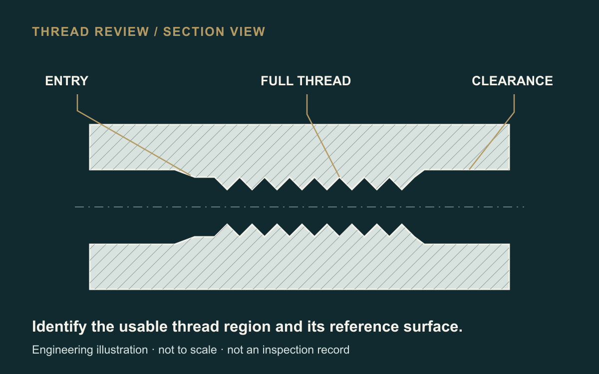
Give the thread system, nominal designation, pitch, handedness and specified fit or limits. Include its usable engagement and the location of the thread relative to the contact face. A section should distinguish the threaded length from an entry chamfer, runout or relief. Supply the corresponding barrel-thread definition so the supplier can review the two parts against the same controlled reference.
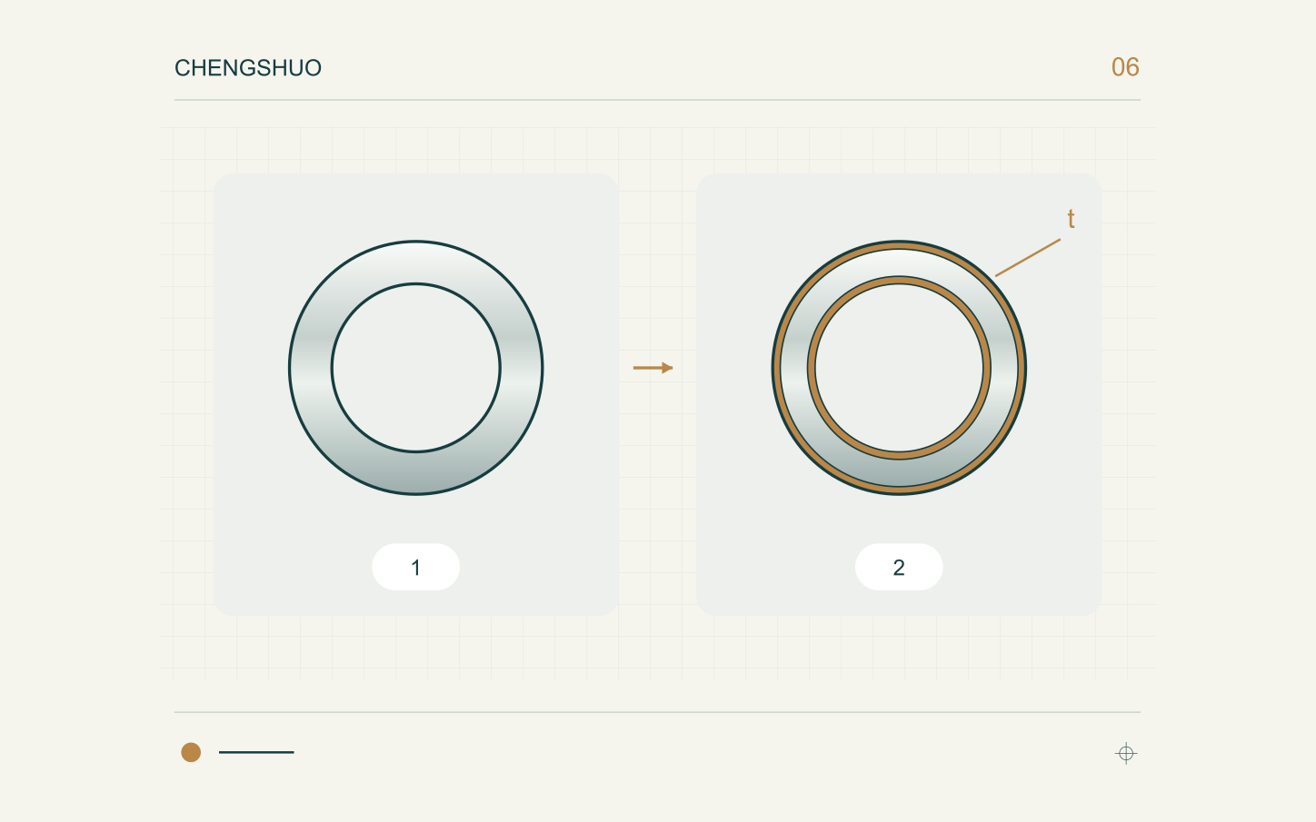
Name the material and final surface treatment where these affect the mating interface. State which dimensional and thread requirements apply after treatment, and identify masked or protected areas if required by the design. Ask the supplier to propose a suitable verification approach for the actual size and access, then agree it before sample manufacture. Retain the agreed thread reference and inspection requirement with the order rather than relying only on a short product description.
Give the contact face and optical opening their own checks
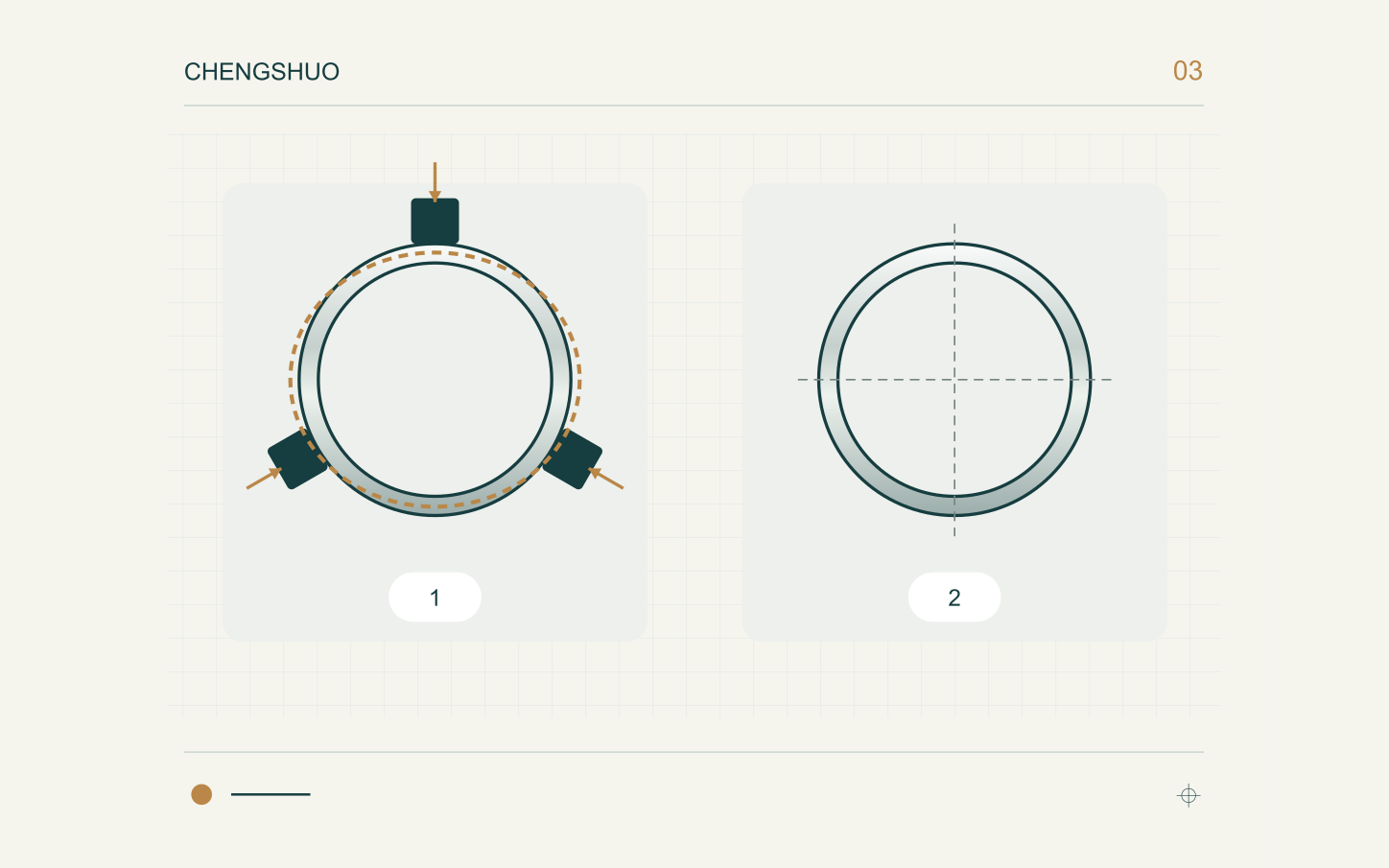
Identify the intended contact land in an enlarged section. Show its boundaries, geometry and relationship to the mating thread and the locating feature used by the assembly. Call out the required edge condition near the optic and make any excluded contact zones visible. Where a chamfer or relief approaches the lens envelope, have the drawing owner confirm that the remaining contact arrangement is the one intended.
Define the clear aperture through the assembled mechanical envelope, not simply as an isolated bore diameter. Include any lens curvature, spacer or installation position needed to review the opening. The optical designer should approve the usable opening and the contact strategy; the manufacturing brief should then translate those approved decisions into identifiable ring features and inspection records. Keep dimensional acceptance for the ring and optical acceptance for the assembled system as separately assigned deliverables.
Review tool slots, remaining wall and access as one detail
Show the installation feature that the selected tool will engage: slots, holes or another controlled feature. Define their position, usable engagement and relation to nearby thread or contact surfaces. Include access around the ring in the assembly view so that a tool can reach the intended feature in the specified installation sequence. Name any edge or debris requirement where tool contact could affect the optical assembly.
Have the assembly designer supply the installation method and any required tightening or retention instruction. Use values approved for the actual optic, contact arrangement, material and assembly; avoid importing a torque from an unrelated catalogue part. Where a separate tool is supplied by another party, identify its controlled interface and owner in the RFQ. This lets the ring, tool and assembly teams work from one revision-controlled detail.
Use a sample plan that answers the open interface questions
A sample review can combine ring dimensions, thread verification and a defined assembly trial with the actual mating reference. Agree the sample identity, barrel reference, stack components and delivered condition before requesting that trial. Specify which results the ring supplier should record and which decisions belong to the optical assembly owner. A concise checklist makes the boundary visible when more than one supplier contributes components.
In a drawing-review example, the ring thread is acceptable but the available slot engagement is obstructed by the chosen barrel. The useful next step is to compare the installation envelope with the controlled tool and ring details, then approve the affected drawing change. Keep the final accepted interface and sample decision available for receiving and repeat manufacture.
| Decision | Agree before ordering | Retain with the order |
|---|---|---|
| Stack definition | Lens, barrel, spacer and ring identities | Approved assembly section |
| Mating thread | Full designation, engagement and final state | Agreed thread verification record |
| Contact zone | Land, reference and edge condition | Feature-linked dimensional results |
| Clear aperture | Approved assembled mechanical opening | Designer-approved interface detail |
| Installation | Tool engagement, access and instruction owner | Controlled tool and ring details |
| Sample release | Trial scope and acceptance responsibilities | Approved sample decision and revisions |
Send the ring and assembly requirements in a usable RFQ
Include the ring drawing, barrel-thread reference, lens envelope and relevant section views. State material, final treatment, quantities and the dimensional, thread and edge records required with the sample. Highlight the contact zone, aperture and installation features so that a supplier can review the machining and inspection scope. Identify who supplies the optic, barrel, spacer and installation tool whenever an assembly trial is requested.
Use the worksheet below to close the decisions before order release. After sample approval, retain the accepted drawing revisions, inspection plan and any assembly-specific instructions as the baseline for repeat orders. If the optic, barrel, coating or tool changes, identify which interface checks must be repeated. Chengshuo can use the controlled ring drawing to discuss the machining brief; optical design limits and acceptance decisions should come from the responsible assembly designer.
Questions before your drawing review
What is the starting document for a lens retaining ring?
Start with a section showing the optic, ring, barrel shoulder and any spacer or compliant element. Add the ring drawing and the mating-thread reference so mechanical contact and access can be reviewed together.
Which thread information should be included?
Include system, nominal designation, pitch, handedness, specified fit or limits and usable engagement. Show the entry, relief and position relative to the contact face in the delivered condition.
Who should approve the contact zone and clear aperture?
The responsible optical assembly designer should approve the lens envelope, contact arrangement and usable opening. The machining drawing should turn these decisions into identifiable features with agreed checks.
Can a generic torque be used for the retaining ring?
Obtain an installation instruction for the actual ring, optic and contact arrangement from the responsible designer. Include that approved instruction and its owner in the sample plan when assembly work is required.
What does the installation-tool review cover?
Review the tool interface, slot or hole engagement, access around the barrel and the installation sequence. Keep the tool and ring details on controlled revisions so a drawing change remains traceable.
Which records help with repeat orders?
Retain the approved ring and mating-interface drawings, final condition, agreed dimensional and thread checks, and the sample-release decision. Record which checks a later optic, coating or tool change affects.
Prepare the drawing review
- Surface roughness on functional faces
- Specify inspection requirements
- Internal corner and relief review
- CNC turning drawing review
Technical references: Thorlabs — retaining rings and lens mounting guide, Thorlabs — fixed lens mounts.