

 5 min read
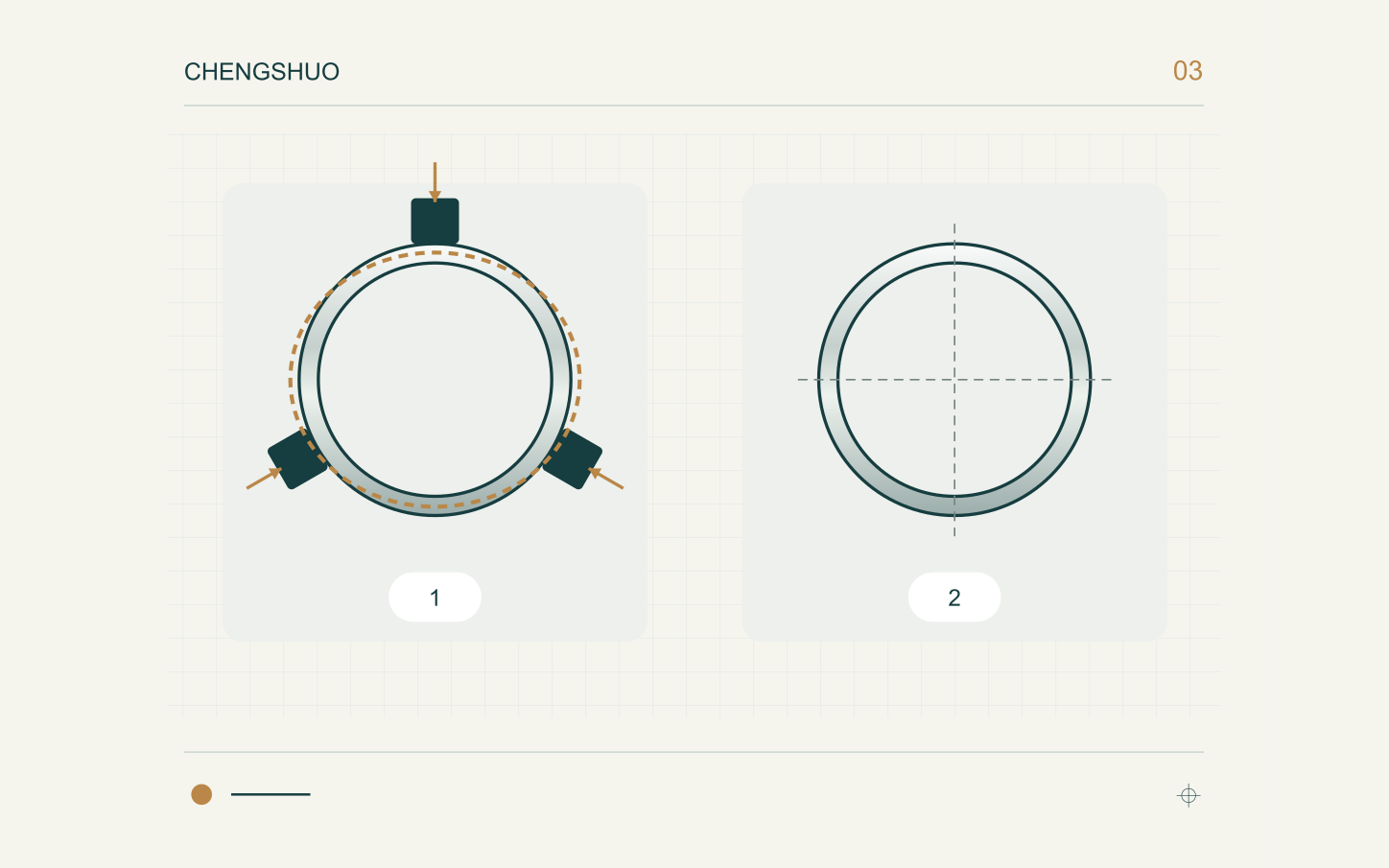
Identify the state in which the tube must conform
Thin-wall tube machining is not defined by a single minimum wall thickness. Diameter, length, material, local grooves and the support arrangement all affect the review. Begin by separating the condition during machining, the free state after release and any specified assembled condition. These states may produce different dimensional observations. A supplier and receiving inspector can disagree even when both instruments are functioning correctly if they restrain the part differently. State which requirements apply in each condition before accepting a sample or changing the inspection method.
Review where the fixture contacts the part
Clamping can change the shape of a compliant tube. SCHUNK explains how distributing clamping positions around thin-walled workpieces reduces deformation in its pendulum-jaw applications. The procurement lesson is to discuss contact location, support length and force distribution, not to prescribe that branded fixture for every sleeve. Ask which surfaces can be gripped and which must remain protected. A wider contact strategy, internal support or another arrangement may be considered, but the actual method must suit cutting loads, access and safe retention.
Review the whole sequence as the wall becomes thinner
The support available at the beginning of machining may disappear after boring, grooving or cutting a cross-hole. Mark the weakest sections and discuss the order in which they are produced. Ask where the part is relocated and whether the final cut occurs before or after a major wall change. Investigate springback or movement after release through the sample plan rather than assuming an in-machine diameter is the delivered result. Any proposed stock, sequence or support change should be evaluated against the same finished drawing requirements.
Define free-state and restrained inspection explicitly
KEYENCE explains that non-rigid parts need clear treatment of free-state and restrained requirements. Where a restraint is specified, identify its contact surfaces, loading method and acceptance basis under the drawing standard. Do not let an inspector squeeze a tube until a preferred reading appears. Record measurement locations and the inspection condition alongside the results. For an assembly-specific requirement, provide the mating geometry and define who supplies the fixture or mating part. A free-state dimensional record and an assembled functional test answer different questions.
Illustrative review: a sleeve with an end groove
Consider a long sleeve with a groove near its open end. This is an illustrative process review, not a Chengshuo production result. An early bore check made while the sleeve is held cannot by itself establish the released shape after the groove is cut. The review could compare readings at agreed axial positions after final machining and release, then perform a separately defined mating check if required. Record the fixture and condition for each result. Do not average away a local departure that the drawing controls individually.
Send a condition-specific sample plan
Send Chengshuo the sectioned drawing, material, quantities and intended acceptance state. Identify negotiable geometry separately from interfaces fixed by the assembly. The review should produce clear questions about support and inspection, followed by an agreed sample scope; it should not turn a generic catalogue tube into proof of a universal thin-wall capability.
- Mark minimum local sections, grooves, openings and protected surfaces.
- Define free-state requirements and any separately restrained requirements.
- Identify grip locations, reference features and measurement positions.
- Agree the final machining, release and inspection sequence for samples.
- Record the actual condition, results and separate assembly-test scope.
FROM THE GUIDE TO YOUR PART
Put the checks into context.


References & further reading

General planning guidance. Feasibility and acceptance criteria are confirmed against your drawing.

