Chengshuo store product visual — drawing-based reference
Shafts & pins / cs-product-038
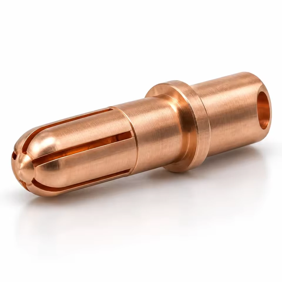
Custom split contact pin to drawing
Source the machined split contact pin with a clear relationship between contact diameter, slot geometry and cable termination. Chengshuo reviews your copper-alloy drawing, mating interface, quantities and requested sample records as one component brief.
Material shown
Copper alloy; exact grade and condition to your drawing
Process reference
Swiss turning, slotting, drilling and edge finishing
Connect the slot definition with the contact and termination
Source the machined split contact pin with a clear relationship between contact diameter, slot geometry and cable termination. Chengshuo reviews your copper-alloy drawing, mating interface, quantities and requested sample records as one component brief.
Identify the current drawing, mating interfaces, requested records and quantity scenarios so the quotation and sample review cover the same component.
BEFORE YOU RELEASE THE DRAWING
A practical next step.
Use these guides to define the records and checks your component needs.
Define the machined contact within the connector assembly
A split contact pin should be sourced with the mating connector information close at hand. Show the working contact region, the stepped body and the termination end in the same controlled drawing package. Identify the mating socket and the features that locate the contact in its housing. State whether the purchase covers the machined contact alone or additional, separately agreed operations. This helps the quotation describe the supplied component precisely and keeps connector assembly decisions assigned to the right owner.
The Chengshuo catalogue reference CS-SW-232 is recorded as a copper-alloy split contact pin with a slotted contact section, stepped body and cable-termination end. Its listed route includes Swiss turning, slotting, drilling and edge finishing. Use that reference to explain the component form, then supply your required alloy grade, material condition and final dimensions. Describe any proposed finish as a specific requirement, including the surfaces and delivered condition to which it applies.
Include the connector designer or responsible assembly reviewer in the technical scope. Mechanical fit, contact insertion behaviour, termination approval and electrical qualification may require different procedures and records. Identify which checks are requested from the component supplier and which are performed on the completed connector. The order can then reference the appropriate acceptance criteria without turning a machined-part description into an unspecified promise about the finished electrical assembly.
Chengshuo catalogue reference CS-SW-232: slotted contact section, stepped body and cable-termination end.
Connect the slot definition with the contact and termination
Define the working contact diameter, its usable length and the transitions into the supporting body. Show the slot pattern with the width, extent and angular relationship required by the design. Add enlarged details where the slot ends or contact edges affect assembly. Distinguish the surfaces that touch the mating socket from the features used only for location or tool access. The drawing should give the machining and inspection reviewers a consistent reference for each important feature.
Specify the termination bore or other termination interface, including depth, steps, access and any edge requirement. Give the intended cable or mating information where it affects the component review. If a subsequent crimping, joining or finishing operation is part of the project, state who performs it and which requirements apply afterward. Show the datum relationship between the contact region, body and termination so the required feature alignment can be discussed before manufacture.
Agree the delivered surface and cleanliness requirements for the actual alloy and finish. Identify important contact edges and any areas that must be protected during handling. Define the sample measurements for contact diameter, slot geometry, termination bore and the relevant geometric relationships. Any mechanical or electrical test should have a named procedure, assembly condition and acceptance owner. Keep those requirements in the purchasing package rather than relying on a broad request for a connector-quality part.
Feature
Enquiry and acceptance
Contact region
Diameter, length and mating socket Record: Dimensional sample results
Slots
Pattern, width, ends and orientation Record: Agreed geometry and edge checks
Termination
Bore, depth and mating cable information Record: Specified termination review
Material and finish
Copper-alloy grade and delivered condition Record: Agreed material or finish record
Functional scope
Actual assembly, method and owner Record: Separately agreed qualification record
Delivery
Protection, separation and lot identification Record: Approved packing and receiving basis
Make sample records usable for assembly and receiving
Send Chengshuo the contact drawing, mating socket or housing information, alloy specification, finish requirement and quantity scenarios. Highlight the contact region, slot ends, termination bore and any feature that needs recorded results. State whether the samples will be reviewed as loose components or in a specific connector assembly. Include the expected documentation and desired timing so the quotation can describe the actual manufacturing and sample-review scope.
Before sample approval, identify the drawing revision, delivered condition and sample identifiers used in each check. Retain dimensional results with any agreed assembly or termination evaluation. The connector owner should record the relevant functional qualification against the actual mating parts and procedure. Where a sample review leads to a change in alloy, slots, finish or termination geometry, issue a controlled update and agree which checks must be repeated for the revised component.
For repeat orders, preserve the approved contact and mating-interface definitions together. Agree part separation, surface protection and lot identification so receiving can trace the delivered components to the accepted sample basis. Review changes to the socket, housing, cable or finishing route before release to manufacture. A clear revision and documentation trail lets purchasing compare repeat supply against the same component requirements without assuming that an unchanged product name means an unchanged connector interface.
What should I send a split-contact-pin manufacturer?
Send the controlled contact drawing, mating socket or housing details, alloy and finish, quantity scenarios and sample requirements. Highlight the contact region, slots and termination interface.
Which alloy and processes are recorded for the reference?
The CS-SW-232 reference lists copper alloy with Swiss turning, slotting, drilling and edge finishing. Specify the exact alloy grade, condition and final requirements for your own component.
How should slot geometry be specified?
Show the slot pattern, width, extent, end details and orientation. Relate those features to the contact surface and to the drawing datums needed for inspection.
How are electrical requirements included in the order?
Name the applicable procedure, actual connector assembly and acceptance owner. Agree which tests belong to the component supply and which qualify the completed connector.
What records should accompany the samples?
Agree the reported contact, slot and termination features, delivered condition and sample identifiers. Keep dimensional and assembly-review results with the drawing revision used.
What needs review when the mating connector changes?
Recheck the contact, slot, housing and termination interfaces together with alloy and finish. Record the design change and agree the affected sample checks before repeat manufacture.
A stainless steel guide pillar with a long cylindrical body and stepped end features. Define the guide diameter, shoulder position and thread engagement for your drawing.
Brass pillar and contact forms with several diameter steps. Share the mating dimensions, engagement length and electrical requirements for your own component.
Use an example to explain your idea. Your own drawing defines the final specification.
FROM COMPONENT TO PROJECT
Review the evidence. Define your part.
Start with the component geometry, then check what the drawing, sample and order records need to establish for your own part.
Send the current drawing with quantities and critical requirements. The review is the starting point for agreeing scope, quotation and sample approval.



 AI-assisted studio view


