 3 min read
Start with the mating parts
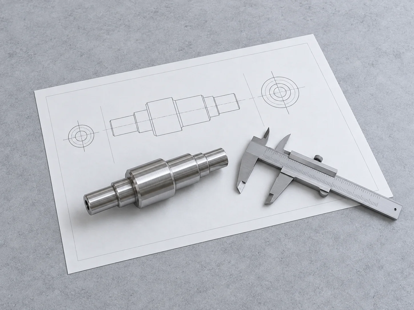
A shaft or pin can look simple while controlling several assembly functions. One diameter may locate a bearing, a shoulder may establish an axial position, and a cross-hole may retain another part. Listing the overall diameter and length does not explain all of those relationships.
Before sending the drawing, identify what each functional feature touches and what movement is intended. Does a surface rotate, slide, locate or remain clear? Does a shoulder establish position or merely provide clearance? Use the answers to check that the drawing expresses the design intent without adding unnecessary restrictions to every surface.
Review size and geometric relationships
List the mating diameters and their limits, then review how the relevant axes and faces relate. A size requirement and a geometric requirement answer different questions. ASME Y14.5 provides a framework for communicating those requirements; the selected controls must be interpreted using the drawing's stated standard and edition.
Identify the datum features and their order where applicable. Ask whether the proposed inspection setup represents the required relationships. Avoid adding a geometric symbol simply because a similar component used it: the feature, tolerance, datum reference and intended function must work together. Resolve ambiguous or conflicting controls with the design owner before manufacture.
Check the details that change assembly
Shoulders, grooves, threads and intersections deserve their own review. For a hypothetical stepped shaft, a mating component may need clearance at the shoulder transition. Identify the permitted transition geometry rather than leaving the supplier to infer it from a shaded model.
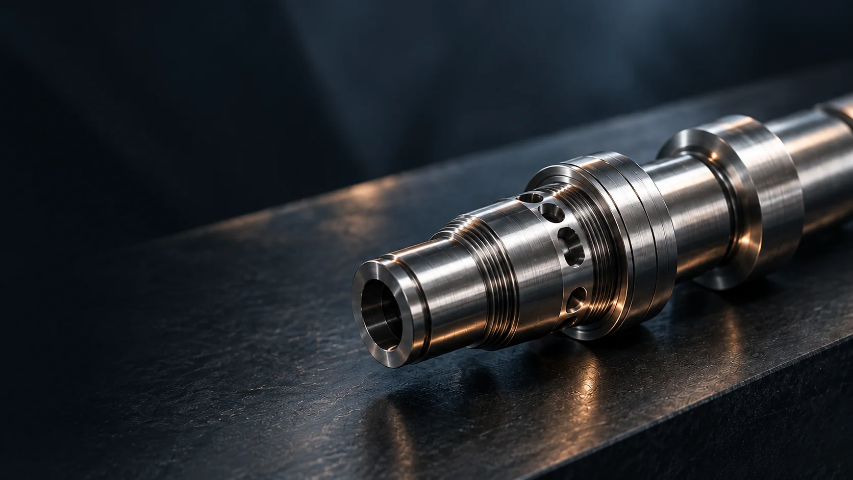
For threaded features, provide the designation, pitch, class where relevant, handedness and effective engagement requirement. For blind features, distinguish the required usable thread or bore from the total drilled depth. Confirm the required condition after finishing and how thread acceptance will be assessed.
- Mark the functional diameter segments instead of applying a vague note to the whole shaft.
- Locate grooves and cross-holes from the intended references.
- Identify surfaces where tool marks, handling marks or edge damage affect use.
- Make retained sharp edges and controlled edge breaks explicit.
Define edges and cleanliness by location
‘Deburr all edges’ is a useful starting note, but it may leave important questions unanswered. A visible outside edge and the intersection of two small holes require different access and review. Identify the locations where residual burrs could obstruct assembly, damage a seal or enter a fluid path.
Specify acceptable edge geometry where it matters and avoid treating a larger chamfer as an automatic improvement. If cleanliness is functionally important, state the applicable requirement and verification method. Photographs can help explain a concern, but they should accompany defined acceptance criteria rather than replace them.
Send a short critical-feature list
Create a numbered list connecting each critical feature to its drawing reference, function, acceptance requirement and proposed verification. Keep noncritical features under the drawing's appropriate general requirements. Any relaxation remains a design change requiring approval.
Include that list with a Chengshuo enquiry for a custom shaft or pin. It helps focus review on the features that determine successful assembly. Material, geometry, quantity and inspection needs must still be assessed together before a particular manufacturing route or capability can be confirmed.
References & further reading

General planning guidance. Feasibility and acceptance criteria are confirmed against your drawing.