

 AI-assisted studio view
cs-product-025
Stainless steel flange plate
A stainless steel flange plate with a central bore and repeated mounting holes. Start with the bolt pattern, mating diameter and mounting-face requirements.
Explore component
Studio image: AI-assisted presentation. Select an original photograph to review the source.
Flanges & covers / cs-product-035
Use this aluminum flange-coupling reference to specify the shaft bore, mounting pattern and flange datum. A drawing-led supplier enquiry connects the mating interfaces with the material, sample inspection and delivery requirements for the actual component.
Send your drawing, quantity and mating-part requirements for a project-specific quotation.
Download review brief
PURCHASING SCOPE
Use this aluminum flange-coupling reference to specify the shaft bore, mounting pattern and flange datum. A drawing-led supplier enquiry connects the mating interfaces with the material, sample inspection and delivery requirements for the actual component.
Identify the current drawing, mating interfaces, requested records and quantity scenarios so the quotation and sample review cover the same component.
BEFORE YOU RELEASE THE DRAWING
Use these guides to define the records and checks your component needs.
Made-to-drawing procurement
Updated
This aluminum flange-coupling reference has a central shaft interface, a flange with mounting holes and an extended end section. A useful purchasing enquiry explains how those features connect to the surrounding assembly. Use the original part photograph to communicate a related form, then define your component through the current drawing and the actual mating-part requirements.
Identify the feature that locates the coupling before specifying the rest of the dimensions. The shaft bore, a shoulder or a flange face may establish the assembly position. Show which relationship controls alignment and which surfaces provide clearance. Include the mating shaft or mounting drawing where it explains the connection and the features that must be inspected together.
Keep drawing number, revision, units and quantity scenarios in one enquiry. State the required aluminum designation and material standard, along with any requested documentation. If several bore or mounting-pattern options are being compared, label each variant clearly. The proposed manufacturing scope can then be reviewed against a controlled specification rather than a general description of a coupling.
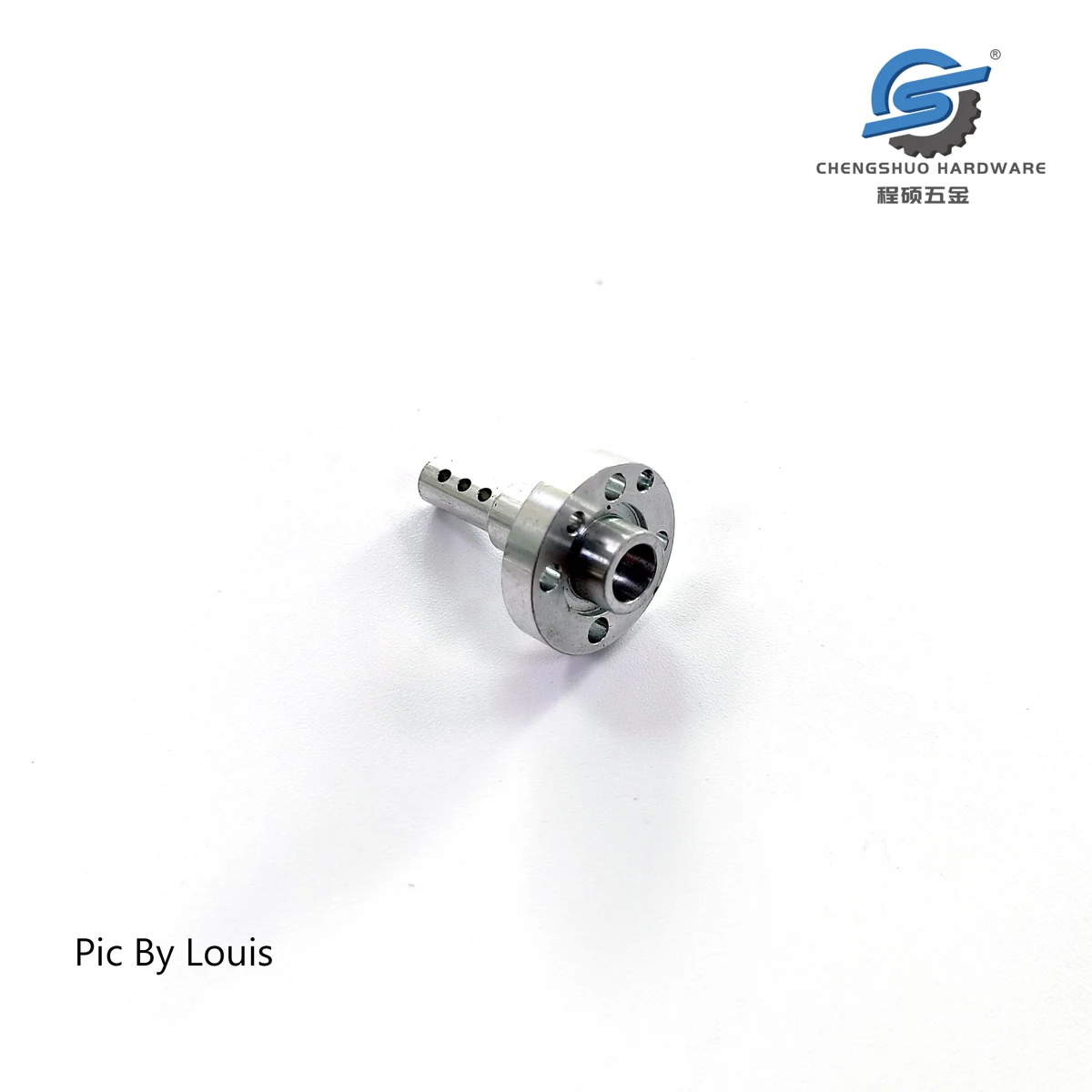
Specify the central bore with the required size, fit and relevant geometric controls. State the length over which the fit applies and identify any relief, groove or edge that affects shaft insertion. Where a supplied mating shaft is used for sample assessment, identify it and describe the agreed checking method. Keep the inspection arrangement linked to the same drawing revision.
For the flange, define the functional face and the reference used to locate the mounting holes. Provide the hole size, pattern and orientation needed by your design. Distinguish clearance holes from any specified threaded features, and show the access required for fastening. If the hole pattern is clocked to another feature, make that angular relationship explicit in the drawing.
Explain the purpose of the extended end section and any steps between the shaft interface and flange. Mark the surfaces that seat against another component and the transitions that need assembly clearance. State the required end condition, surface requirements and treatment scope for your project. Identify whether final dimensions apply before or after a requested surface operation.
Choose acceptance checks that reflect the actual assembly requirement. Bore size, flange-face relationship and mounting-hole position can be listed as separate characteristics with an agreed method and record. If the application calls for an additional functional or assembly test, supply its conditions and acceptance criteria. The quotation should distinguish component measurements from any separately agreed system-level verification.
| Feature | Enquiry and acceptance |
|---|---|
| Shaft bore | Fit, engagement length and edge condition Record: Agreed bore measurement |
| Flange face | Functional face and datum relationship Record: Drawing-based geometric check |
| Mounting pattern | Hole size, location and orientation Record: Pattern check to specified datums |
| Extended end | Seating surfaces and assembly clearance Record: Selected interface measurements |
| Surface state | Required material and delivered condition Record: Agreed project records |
| Delivery | Variant identity and protected surfaces Record: Receiving and packaging review |
Use the first sample review to confirm the important interfaces rather than an unspecified overall impression. List the drawing characteristics that decide acceptance and the results you need recorded. A buyer-supplied fixture or mating component can support this review when its identity, condition and checking procedure are agreed. Record any approved change with the drawing revision.
Provide sample quantity, the first order quantity, further volume scenarios and delivery destination. Explain identification and protection requirements for the bore, locating faces and mounting features. Include any requested material or inspection documents in the enquiry. Several similar variants should remain separately identified through quotation, sample review and receiving so their interfaces are not confused.
The drawing-review enquiry link carries this flange-coupling reference into your brief. Add your actual material, dimensions, mating arrangement and quantity options. Share authorised drawings, with confidentiality terms agreed where required. Before ordering, check that the offered component, additional operations, documentation and acceptance plan describe the same revision and the same scope of supply.
The Chengshuo reference shows a bored aluminum coupling with a flange, mounting holes and an extended end section. Your own drawing defines the material designation, interfaces and acceptance requirements for the requested part.
Provide the required bore size, fit, engagement length and edge condition. Identify the locating datum and any mating shaft or fixture used for sample assessment, including the agreed inspection procedure.
Show their size, pattern and orientation to the flange datum. Distinguish the required hole types and mark any angular relationship to another feature, along with the access needed for fastening.
Select the characteristics that decide the assembly fit, such as bore size, flange-face relationship and hole position. Agree the measurement methods and the results to be recorded before the sample is accepted.
Supply the actual test method, conditions, assembly arrangement and acceptance rule. State which checks concern the loose component and which require an assembled system or buyer-provided equipment.
Send the controlled drawing, material specification, sample and order quantities, delivery destination and documentation requirements. List alternative bores or mounting patterns as separate variants so each scope can be compared.
AI-assisted studio viewA stainless steel flange plate with a central bore and repeated mounting holes. Start with the bolt pattern, mating diameter and mounting-face requirements.
Explore component AI-assisted studio view
An aluminum flange seat with a central bore and a patterned mounting face. Define the face datum and the location of holes and slots from that reference.
Explore component AI-assisted studio view
A stainless steel connector with an angled body and round mounting features. Identify the mating faces, bore and critical hole positions for your version.
Explore componentFROM EXAMPLE TO YOUR REQUIREMENT
Use an example to explain your idea.
Your own drawing defines the final specification.
FROM COMPONENT TO PROJECT
Start with the component geometry, then check what the drawing, sample and order records need to establish for your own part.
Send the current drawing with quantities and critical requirements. The review is the starting point for agreeing scope, quotation and sample approval.
Request a drawing review