 4 min read
Why can a two-hole fixture bind during loading?
A part that must be pushed hard onto two fixture pins deserves a locating review before a tighter pin tolerance is ordered. Hole size, hole spacing, pin spacing and the chosen clearance all belong to the same assembly. If two full round pins attempt to establish the same constraint, spacing variation can prevent smooth loading. Begin with a plan view of the workpiece and fixture, showing both hole axes, the supporting face and the intended orientation. Ordering two accurately made pins separately does not establish that the combined locating system will work.
Why pair a diamond pin with a round locating pin?
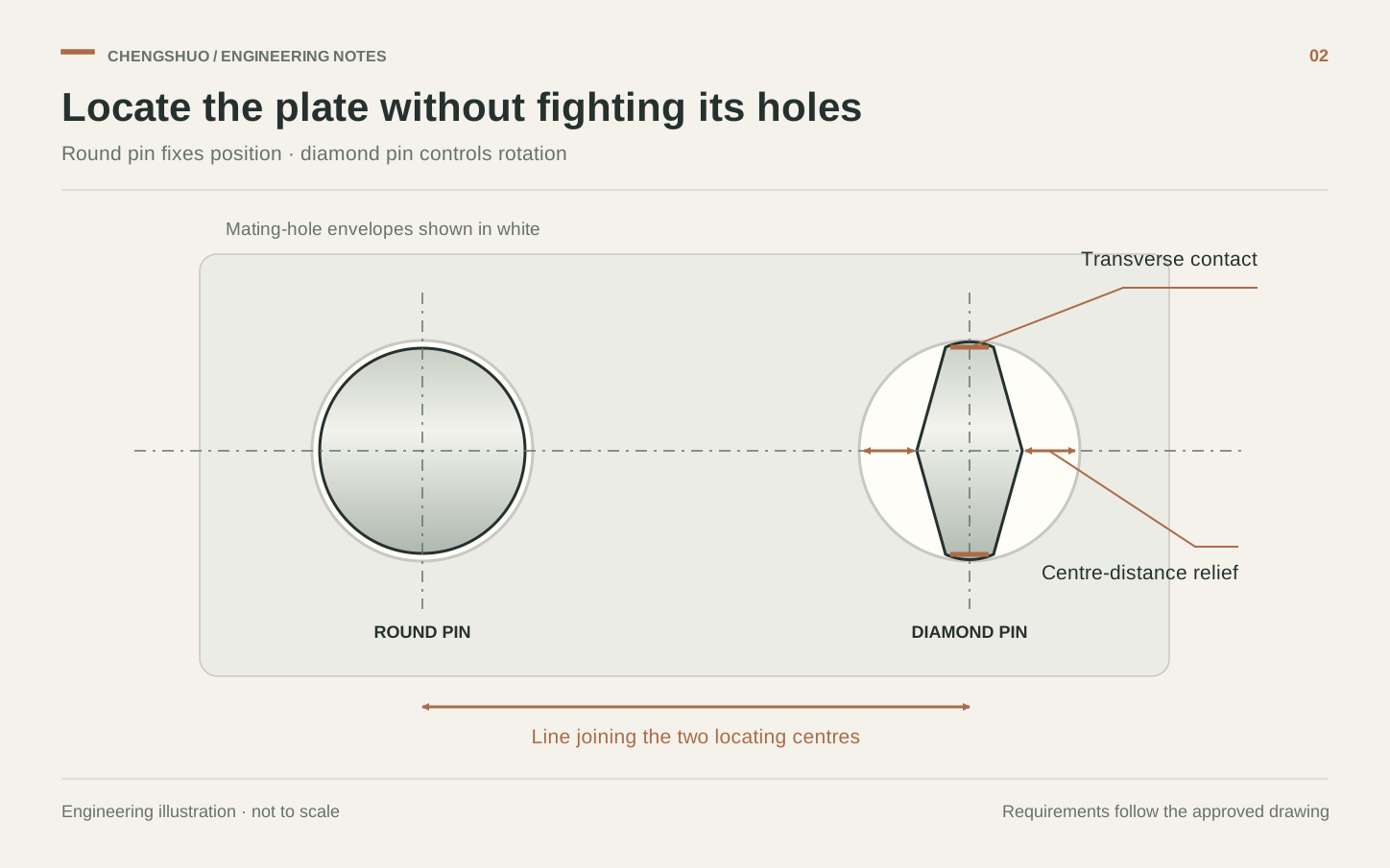
Carr Lane describes a round pin as the primary locator in two axes and a relieved diamond pin as the secondary locator in one axis. In a typical two-hole arrangement, the relieved direction accommodates centre-distance variation, while the working width across the other direction controls rotation about the round pin. This pairing concerns location within the mounting plane. The support face and clamping arrangement still need their own definition. A diamond-shaped appearance is therefore insufficient: the drawing must identify which surfaces locate and which surfaces intentionally provide clearance.
Which dimensions and orientation must the drawing control?
Show the line between the two pin centres and relate the diamond pin's relief direction to that line. A ninety-degree installation error can defeat the intended clearance. For a custom pin, include a way to identify or maintain its installed orientation, together with the shank fit and mounting depth. Specify the locating height above the support and the lead-in needed for loading. If heat treatment or coating is required, identify the final acceptance condition for the locating surfaces and mounting shank. Avoid dimensions that leave the functional width defined only in the unfinished state.
How should centre-distance variation be reviewed?
Imagine a removable plate whose two hole centres and the fixture's two pin centres are both nominally 80 mm apart. The nominal match does not show how their tolerances combine. Prepare a worst-case comparison using the controlled hole positions, pin positions and minimum clearances, then assess the diamond relief in the direction that must accommodate the mismatch. This is an illustrative review method, not a calculated design for an unidentified fixture. If the plate must also resist significant working forces, give the fixture designer the load path rather than assuming that any locating pin is an adequate stop.
Can a replacement pin be accepted from diameter alone?
No. A single diameter reading cannot describe a relieved diamond head or its installed orientation. Record the round pin's working diameter, the diamond pin's working and relieved widths, and their relationship to the support in the finished condition. Use the inspection-record checklist to connect each result to the pin drawing revision and sample identity. Separately agree any loading and removal trial, its identified mating parts or checking fixture, and the cleanliness, coating state and clamp sequence. A loose-pin report and an installed-pair trial cover different acceptance scopes.
What should a custom locating-pin RFQ include?
Send Chengshuo the fixture sketch and individual pin drawings with revisions, material, finished condition and sample or order quantities. Identify whether you need one replacement, a new pair or a machining-only quotation; name the mating geometry used for review and who accepts any assembly trial. Use the shaft-and-bushing fit checklist to distinguish the mounting fit from the working locating surfaces. Include these inputs so the quote covers the agreed component and inspection scope.
- Workpiece hole sizes and positions, support plane and required loading direction.
- Round working diameter, diamond working width and defined relief direction.
- Installed centre distance, orientation feature, shank fit and locating height.
- Material, heat treatment, finish and acceptance in the finished condition.
- Sample measurement records, mating-part trial and replacement identification.
FROM THE GUIDE TO YOUR PART
Put the checks into context.
Request a drawing review
References & further reading

General planning guidance. Feasibility and acceptance criteria are confirmed against your drawing.