Skip to content
CHENGSHUOPRECISION
EN
Request a drawing review

Sensors & instrumentation / APPLICATION STUDY

Small instrument pins need more than a diameter callout

Clarify locating features, insertion edges and material or finish requirements without assuming a photographed pin has a proven sensing or electrical function.

EngineeringPurchasing
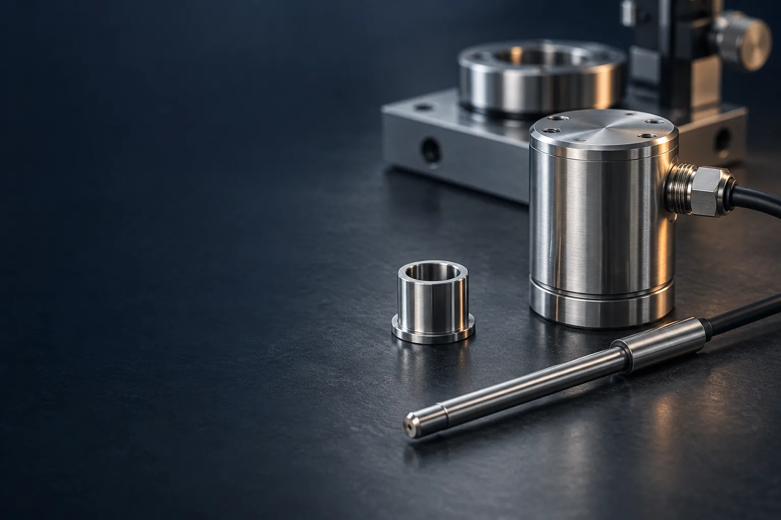
Illustrative Sensors & instrumentation component application
Application illustration · component references below

01 / THE CUSTOMER PROBLEM

Where projects
can get stuck.

A small pin for an instrument or electromechanical assembly may have several jobs that are difficult to see in a product image: locating another component, setting an insertion depth or maintaining clearance. Some designs also carry electrical or environmental requirements, but those must come from the customer specification. Begin by separating the mechanical interfaces from any additional function. A familiar pin shape is useful for discussing geometry; it is not a qualification for an instrument.

Questions to resolve early

  • The material family is treated as sufficient evidence of an electrical, magnetic or environmental property.
  • A permitted cosmetic variation is confused with damage on a locating surface or a functional contact region.
  • An insertion test passes once, but the drawing does not identify the feature or condition responsible for acceptance.

02 / A PRACTICAL REVIEW ROUTE

Work through the
requirement, step by step.

01Identify the insertion and locating features

Annotate the pin end, lead-in, locating diameter, shoulder and retained region. Describe how the mating component is assembled and which edges it contacts. If position or insertion depth is important, identify the surfaces that control it. Avoid leaving the supplier to infer a fit, retention method or allowable edge condition from the model alone.

02Specify material and finish by requirement

Give the material grade, standard and condition rather than just brass or stainless steel. Where plating, passivation or another finish is needed, identify the specification, treated areas and final acceptance state. If conductivity, magnetic response or corrosion behavior matters, supply the actual requirement and agreed verification route instead of using appearance as evidence.

03Plan handling and sample evaluation

Discuss how small features will be inspected and protected through finishing, packing and assembly. Mark any region where a burr or handling mark would interfere with insertion. Define a sample evaluation that records both drawing results and the relevant customer assembly observation. Assign responsibility for tests that require the complete instrument or mating components.

03 / BEFORE ACCEPTANCE

Agree what
the evidence should show.

A general promise of precision is not a project acceptance plan. Confirm the checks and records that apply to your component.

  • Confirm the specified locating diameters, shoulder positions, insertion edges and finish condition on the approved sample.
  • Connect any material or treatment document requested to the relevant delivered sample or batch.
  • Record the assembly test setup and its limited conclusion; retain open requirements for separate verification.

04 / REAL COMPONENT REFERENCES

Connect the topic
to the geometry.

Sensor and instrumentation use is a candidate application context, not a documented Chengshuo customer outcome. The referenced pin and shaft establish published geometry only; material grades, coatings, performance and customer approvals are not established by those examples.

05 / YOUR PROJECT CHECKLIST

Prepare the details
that move the review forward.

Tick off the information you have, then use this checklist to prepare your enquiry.

Project information to prepare
Use this brief in my enquiry

PROJECT QUESTIONS

Before you send
the next revision.

Is the brass thimble pin a verified sensor contact?

No. Its published page identifies a brass pin and automatic-lathe machining, while photographs show stepped geometry. That evidence does not establish electrical contact performance, sensor use or compatibility with your instrument.

Can sourcing approve a different alloy to reduce cost?

Treat it as a proposed change. Identify the affected mechanical, finishing and additional functional requirements, then obtain approval from the responsible design authority before the quotation or order uses the alternative material.

Evidence and scope of this study

Sensor and instrumentation use is a candidate application context, not a documented Chengshuo customer outcome. The referenced pin and shaft establish published geometry only; material grades, coatings, performance and customer approvals are not established by those examples.

The proposed application is a review scenario. Final feasibility, performance, inspection scope, price and delivery conditions require confirmation against your current drawing.


TURN THE STUDY INTO YOUR OWN BRIEF

Does this sound
like your component?

Your enquiry will include this review topic and the relevant product references. Edit the brief to fit your drawing.

Discuss this requirementDownload review checklist

CONTINUE THE REVIEW

Related project questions.

Automation & motion / APPLICATION STUDY

Shaft fit & assembly alignment

Connect shaft diameters, shoulders and grooves to the mating assembly, then define the datum setup and acceptance checks before quoting.

EngineeringQuality

Start the review with

  1. Map the mating interfaces

    Mark the bearing or sleeve contact, locating shoulder, retained end and any clearance-only regions on an annotated view. Include the relevant mating-part requirements, not necessarily the entire assembly model. Identify whether a groove locates another component or merely provides clearance. This makes it possible to discuss each feature against its actual job.

  2. Resolve the drawing references

    Identify the applicable drawing standard and revision, then confirm datum features, their order and the geometric controls required by the design. Ask how the same references will be established during inspection. Record questions about incomplete or conflicting callouts instead of translating an informal request for concentricity into a different requirement without approval.

  3. Review the complete manufacturing condition

    Ask the supplier to review support, access to shoulders, secondary features and the state in which final checks occur. A Swiss-type route may be a candidate for a slender turned part; the drawing, material and actual equipment configuration determine suitability. If heat treatment or coating is specified, identify which requirements apply after that operation.

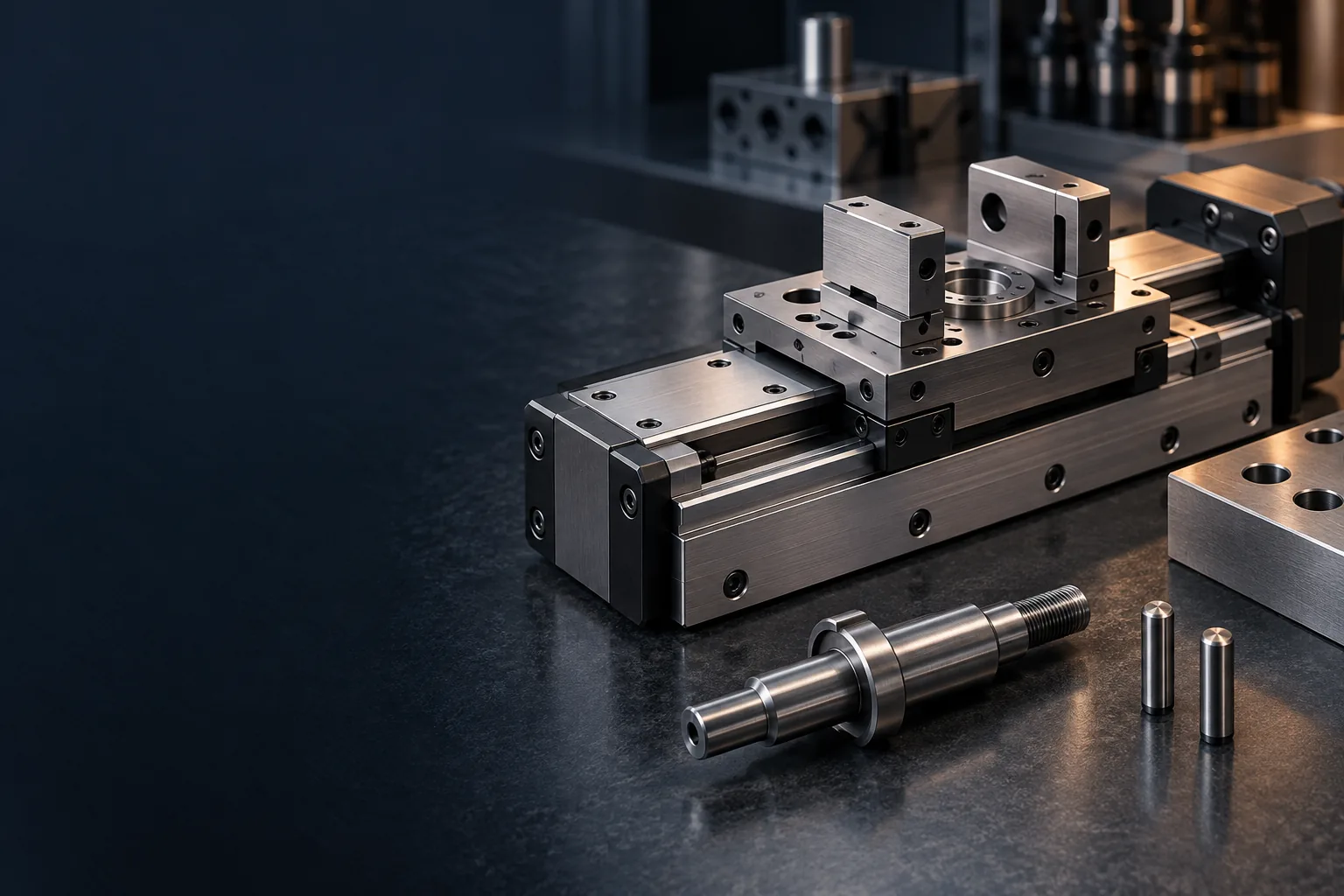
The linked Chengshuo shaft and pin are published geometry references. They do not establish a completed motion-system application, measured alignment result or verified process capability. This guide is a project-review framework, not a customer case report.

Automation & motion / APPLICATION STUDY

Sleeve fit & thin-wall interfaces

Separate bore, outside diameter and installation conditions so a sleeve can be reviewed against the way it will actually be assembled and measured.

EngineeringQuality

Start the review with

  1. Separate the functional surfaces

    Mark the bore, outside locating surface, flange seat and clearance regions. Supply the relevant housing and shaft requirements where they influence acceptance. Identify whether the sleeve is a spacer, guide or another type of component in your assembly; that function is a customer input, not something established by the example product name.

  2. Define the measurement condition

    State whether sizes and geometric requirements apply to the free part, a specified restrained condition or the installed assembly. Agree how the part will be held without obscuring the characteristic being checked. Where suppliers and incoming inspection use different methods, compare those methods before approving a sample report.

  3. Review edges, finishing and protection

    Identify insertion edges, transitions and any surface that must remain free of handling marks. Confirm finishing specifications, permitted edge breaks and the point at which final dimensions are accepted. Discuss the proposed machining and measurement approach for the actual wall geometry. Agree protective packaging where contact between parts could affect a specified surface.

The brass sleeve and aluminum washer links document published component forms. The washer is an annular geometry reference, not evidence of a sleeve application. Installation behavior, thin-wall limits and measurement results require project-specific review.

Fluid control & equipment / APPLICATION STUDY

Internal burrs & cleanliness

Turn a general deburring note into named internal features, inspection access and agreed cleanliness evidence for small bored components.

EngineeringQuality

Start the review with

  1. Locate the hidden intersections

    Provide section views for cross-holes, bore ends, recesses and any other region that cannot be judged externally. Mark the boundaries of the required edge condition, including edges that must retain their designed geometry. Ask the supplier to review tool access, removal access and inspection access as separate questions before confirming the route.

  2. Make the acceptance language observable

    Replace ambiguous terms with the customer specification or an agreed, reviewable criterion. Define permitted edge changes and prohibited damage to adjacent surfaces. Where direct visual access is limited, agree the method and coverage needed to assess that feature. Reference images can clarify appearance, but should not silently replace a dimensional or cleanliness requirement.

  3. Define cleaning and protection as a scope

    Identify required cleanliness criteria, relevant process restrictions, verification evidence and the condition at delivery. Confirm whether inspection or handling occurs after cleaning, and how accepted parts remain protected. If a test requires special equipment or external support, establish responsibility and feasibility before treating it as included. Do not adopt a universal cleanliness grade without an application requirement.

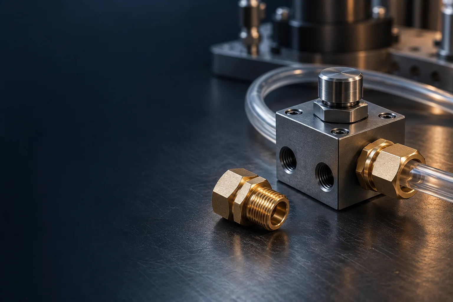
Published photos show external openings on the referenced coupling and valve joint. They do not reveal all internal geometry or prove deburring, cleanliness or fluid-service performance. The internal-feature scenarios here are review prompts for the buyer’s own drawing.

From drawing to project review.

Read the film transcript

Start with your drawing. Define material and finish. Identify critical features. Align samples and production quantities. Request a project review. Illustrative renders and Chengshuo component photography; this is a project overview, not machining footage.

Discuss your drawing

CHENGSHUO / PROCESS FILMS

Process film

Silent process film. Workshop footage is process context; it is not a record for the reference component.

View original