 4 min read
Updated
Locate the hole along the shaft and around its axis
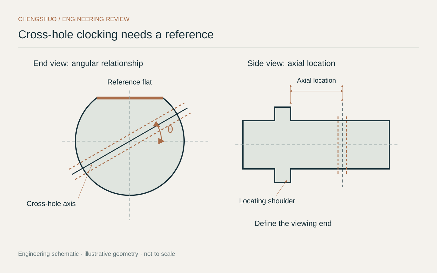
A cross-drilled shaft can have the required hole diameter and axial distance while still needing a separate angular relationship for assembly. Show the hole centre position from the specified axial datum, then identify the feature that establishes its clocking. The drawing review should make both relationships visible so the quotation addresses the complete interface.
Start the enquiry with the controlled drawing and revision. Include the shaft, its cross-hole and the feature that must align with it in the same view or in clearly related views. Describe the mating arrangement and identify which surfaces locate the shaft during use. A purchasing note such as align hole to slot becomes useful when the slot and the required relationship are fully defined.
Choose a functional clocking reference
A flat, keyway or another controlled hole can provide the named reference for an angular relationship when it matches the assembly design. Identify the actual feature and the applicable drawing requirement. If the drawing uses a datum system, keep its symbols and references consistent across the shaft detail, assembly view and inspection worksheet.
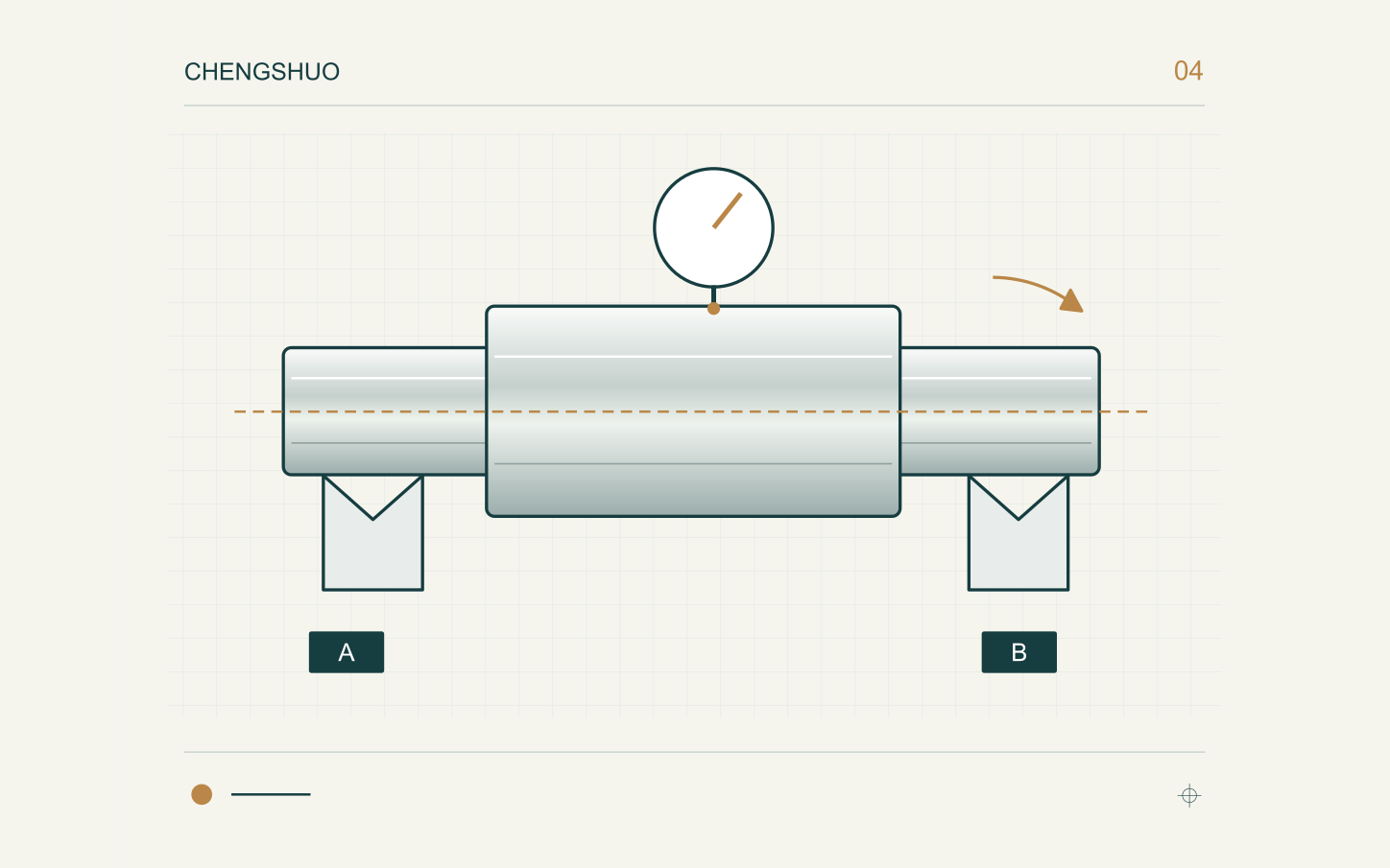
Carr Lane's locating guide distinguishes concentric location from radial location, which restricts rotational movement. Use that distinction when discussing how a cylindrical shaft will be oriented during a check. The component drawing defines the required relationship; the proposed fixture or measuring setup should then explain how the named reference is established for the agreed result.
Describe intersecting features and the finished edge condition
Show whether the cross-hole reaches an internal bore, intersects a groove or passes through more than one wall. Include the relevant section and the locations where edges need an agreed acceptance condition. This lets the drawing review consider the complete opening and the access needed for the requested finishing and inspection work.
Separate the hole's size requirement from its position and from the edge condition. If a pin or fastener passes through the assembly, identify the mating item and its drawing revision where it is part of sample approval. Describe the intended lead-in or clearance rather than leaving a supplier to infer it from an unlabelled photograph.
Keep the reference consistent between operations
Ask how the proposed manufacturing route maintains the relationship between the cross-hole and the other functional features. The enquiry should identify which features control assembly, while the supplier explains the proposed setup and the drawing points requiring clarification. A change in setup can then be discussed in terms of the required interface rather than an assumed machine arrangement.
If another supplier provides a mating part or an earlier operation, name the supplied item and the condition in which it is received. Include the documents used to identify its reference features. Agree how a drawing revision is communicated across the handoff so a cross-hole is checked against the same reference used for the mating slot, flat or fastening feature.
Agree what the sample report will demonstrate
Assign drawing characteristic numbers to hole diameter, axial location and angular relationship. State the required part condition and the agreed reference setup. If the acceptance record includes a geometric measurement, identify the expected result and the relevant drawing requirement. If a trial assembly is also requested, give it its own scope and acceptance rule.
Record the identity of any provided pin, hub or fixture used in that trial. Note the shaft revision and the condition in which the assembly was assessed. Where results differ between inspection locations, compare the actual reference features and setup before treating the records as equivalent. An open point should lead to an explicit clarification and a controlled approval decision.
Prepare an enquiry for the complete shaft interface
Send Chengshuo the latest shaft drawing, material specification and quantity options. Mark the cross-hole, the axial reference and the feature controlling rotation. Include end features, threads, requested surface operations and the sample records needed by your quality team. An assembly view is helpful when the installation sequence explains why a particular angular relationship matters.
Use a published shaft reference to identify the general part form, then attach the requirements for your own component. Ask for unresolved drawing points to be identified during quotation review. Keep the approved revision and inspection scope with the purchasing record so a later quantity change or repeat order continues from the same agreed interface.
Enquiry and acceptance worksheet
| Item | Enquiry and acceptance |
|---|---|
| Hole size | Specify the diameter limits separately from location and orientation. |
| Axial location | Name the axial datum and the hole centre position. |
| Clocking | Identify the flat, keyway or other controlled angular reference. |
| Intersections | Show internal bores, grooves, wall openings and required edge condition. |
| Sample record | Associate each result and any assembly trial with its drawing characteristic. |
Questions before your shaft enquiry
Does a shaft diameter establish the angular position of a cross-hole?
The enquiry also needs a named clocking reference and the required relationship to that feature. Show the functional interface on the controlled drawing.
Which feature can be used for clocking?
Use the flat, keyway or other controlled feature selected by the assembly design. Keep its designation consistent in the drawing and the agreed inspection setup.
How should an intersecting bore be shown?
Add a section view identifying the intersection, the required edges and any access limitations relevant to finishing or checking the part.
Can a mating pin be used in sample approval?
Identify the pin and agree its role, the assembly condition and the acceptance rule. Keep a trial assembly separate from the specified geometric measurement results.
What should the inspection record identify?
Include drawing revision, characteristic numbers, part condition and the reference setup used for the results. Identify any mating pieces used in an agreed trial.
What should I send for a cross-drilled shaft quotation?
Provide the drawing, material, quantities, critical hole relationships, requested finishing and required sample documents. Add an assembly view where it clarifies the interface.
Move from the drawing review to a part enquiry
- Shaft and pin reference parts
- Original stainless steel shaft reference
- Define internal cross-hole edge acceptance
- Prepare a machining RFQ
Technical source: Carr Lane — Guide to Locating and Clamping Principles. Read on .
FROM THE GUIDE TO YOUR PART
Put the checks into context.


References & further reading

General planning guidance. Feasibility and acceptance criteria are confirmed against your drawing.