 4 min read
A correct diameter does not establish shoulder seating
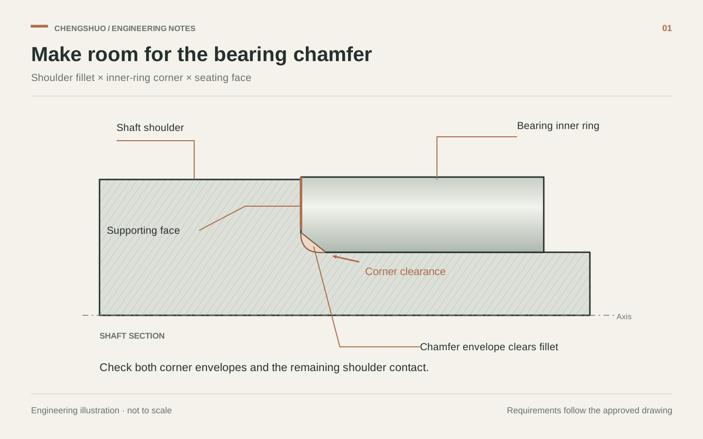
When sourcing a stepped bearing shaft, inspect the corner where the journal meets its shoulder. A shaft may satisfy the journal diameter limits while its fillet contacts the bearing corner before the bearing face reaches the abutment. The resulting gap changes the intended axial stack. Start the RFQ with the actual bearing designation and its mounting information, alongside the controlled shaft drawing. A generic bearing outline copied into an assembly model is useful for layout, but it should not become the acceptance definition for this small and consequential interface.
Compare the permitted corner envelopes
NSK's mounting guidance calls for clearance between the shaft or housing fillet and the bearing chamfer, and discusses shoulder support as a separate requirement. SKF product tables likewise distinguish bearing chamfer dimensions from maximum permissible abutment fillets. Use the selected bearing's current table and drawing rather than treating a catalogue chamfer value as a shop instruction to copy directly. Review radial and axial clearance around the whole corner, including a specified relief if present. This is a fit between two profiles, not simply a comparison of two nominal diameters.
Keep the supporting face and manufacturing route connected
Mark the annular face that must support the bearing and show any nearby seal, spacer or removal access. The quote should identify whether the journal and shoulder are accepted after turning, grinding or a later surface process. If a tool cannot produce the specified corner while preserving the adjacent surface, request a drawing decision before machining. An undercut can provide clearance, but adding one also changes the shaft section and nearby geometry. Record its approved profile and location instead of allowing an unspecified tool relief to become a production feature.
Illustrative review: the radius passes, but the interface does not
Consider a drawing that permits a shoulder radius of 0.6 to 0.8 mm, while the chosen bearing's installation drawing permits a maximum shaft fillet of 0.6 mm. This invented review example exposes a document conflict: a shaft at 0.8 mm can conform to its drawing without satisfying the bearing interface. The buyer should resolve that conflict with the design owner before comparing suppliers. Possible revisions include an approved smaller corner or a separately assessed relief. Neither machining a sample nor tightening the assembly harder resolves the underlying mismatch between the two documents.
Agree the evidence for the corner and the seat
Add the corner profile and shoulder location to the sample inspection plan, with feature identifiers that match the drawing. Select a profile measurement method suited to the accessible geometry, and agree how the shoulder face will be evaluated against its stated reference. Where an assembly seating check is required, identify the mating bearing, mounting condition and permitted gap or contact criterion. Keep that check distinct from dimensional inspection. A successful seating trial does not, by itself, document the shaft's bearing life, operating temperature or performance under service load.
Send the shaft and bearing interface for review
For a Chengshuo machining review, send the shaft drawing and the selected bearing's mounting sheet together. That lets the discussion focus on a usable production definition before the order is placed. Include the following items so that a quotation covers the interface you intend to assemble.
- Bearing designation, mounting drawing revision and permitted abutment envelope.
- Journal limits, shoulder location, contact diameter and corner or relief profile.
- Material, heat treatment and final surface process for the shaft.
- Profile and shoulder inspection requirements, with sample quantities.
- Assembly seating criterion and approval responsibility for any proposed change.
FROM THE GUIDE TO YOUR PART
Put the checks into context.
Request a drawing review
References & further reading
- NSK — Rolling Bearings for Industrial Machinery, section 13.2: shoulder and fillet dimensions

- SKF — Dimensions and abutment and fillet dimensions
General planning guidance. Feasibility and acceptance criteria are confirmed against your drawing.