

 6 min read
Specify each end of a custom fitting by its complete thread designation and applicable standard, then show the mating port and intended sealing interface. “BSP”, a nominal inch size or a photograph alone does not give a machinist a complete manufacturing definition.
For OEM buyers, the drawing must define the connection the equipment needs. Use this guide to turn an uncertain thread description into a drawing review and quotation brief.
Start with the connection, not a familiar abbreviation
An RFQ reading “make this brass fitting, BSP thread, same as sample” leaves several decisions open. Which end is being described? What is the full thread callout? Which port drawing governs the other half? Where is the seal intended to form? A quote based on different answers is difficult to compare, even when suppliers use the same material description.
Label the ends A and B on the current drawing. For each end, attach the complete designation, governing standard and required edition. If the purchased port and your component drawing disagree, record the conflict for the design owner instead of asking the supplier to choose silently. A photograph is useful for orientation; it is not a replacement for those definitions.
If only a physical sample exists, separate observed features from confirmed requirements. Record whether it has an internal or external thread, the apparent parallel or tapered form, and any visible sealing surface. Keep an unidentified thread marked “identity to confirm” until the responsible engineer establishes the drawing basis. Do not force a trial assembly to resolve uncertainty.
Separate the thread family from the sealing interface
ISO 228-1 covers parallel fastening pipe threads. A pressure-tight assembly using that family needs its sealing arrangement outside the thread to be defined. ISO 7-1 addresses the separate family in which the threaded connection provides the sealing basis. NPT belongs to the ASME B1.20.1 pipe-thread system, whose scope includes thread dimensions and gauging. These references describe different design bases; none approves a particular pair in your machine.
Use the following comparison to ask for the missing definition. It is a purchasing review aid, not a dimension table or an interchangeability chart.
| Information on the RFQ | What it establishes | What still needs confirmation |
|---|---|---|
| G / BSPP with ISO 228-1 identified | A parallel fastening-thread family | Full designation, mating connection and separate sealing geometry |
| ISO 7-1 identified | A thread-sealing pipe-thread design basis | Complete callouts for both ends, their approved pairing and assembly requirements |
| NPT with ASME B1.20.1 identified | The specified NPT thread family | Full designation, mating end and the connection-specific sealing and assembly scope |
| “BSP”, an inch size or a sample photo | A starting reference for identification | Thread family, standard, complete designation and seal definition remain open |
Parallel or tapered form is an identification step, not the whole specification. The Swagelok identification guide separates thread identification from end-connection identification and warns that its reference tables are not inspection acceptance criteria. Treat similar diameters or apparent engagement as clues, not evidence of a compatible pair.
Show where the connection is meant to seal
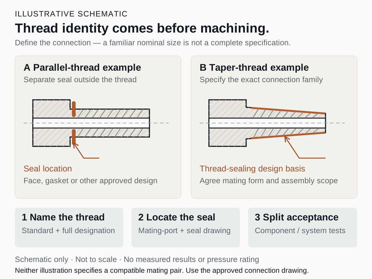
Mark the intended sealing location on a section view of the actual connection. Where the design uses a separate seal, show its location, the relevant contact surfaces and the specified sealing element. Where the approved design relies on the threaded connection, identify that basis and the corresponding mating form. The schematic above illustrates questions to resolve, not a choice of seal for your application.
For machining review, identify the surfaces whose condition matters: a seating face, shoulder, groove, bore entrance or other specified interface. Add the applicable surface, edge and geometric requirements to the controlled drawing. An attractive external thread does not define a sealing face, and a smooth-looking face does not establish a specified surface finish.
Provide the material and final treatment state as well. If plating or another finish is required, state which final features and thread checks govern acceptance. Keep seal material, fluid compatibility and operating conditions with the design requirements; do not infer them from the fitting material or from another product's catalogue.
Agree component checks and system tests separately
Once the identity is confirmed, agree how the machined component will be accepted. The review should name the thread requirement, inspection basis, final condition and required records. For ordinary straight-thread gauge questions, use the existing threaded-sleeve inspection guide. Its scope is not a substitute for a pipe-thread-specific inspection plan.
A component inspection record and a leak or pressure test answer different questions. If your project needs a system test, define its procedure, conditions, acceptance criteria, test article and responsible party as a separate quoted scope. Do not assume it is included in a machining enquiry. A gauge result alone should not be presented as a pressure or leak-test result.
This separation also makes sample approval more useful. Reference the drawing revision and the accepted inspection scope when approving a sample. If a sealing surface, mating port or treatment changes later, send the change for review rather than treating the old sample as approval of the revised connection.
Turn the uncertainty into a usable RFQ brief
Before requesting a quote, check that each end has a complete designation and standard; both mating drawings have revisions; the seal location and relevant surfaces are marked; material and final treatment are stated; component inspection records are identified; and any system-test responsibility is explicit. Open items can remain in the brief, provided they are clearly marked for engineering confirmation.
For geometry references, compare the shoulders and openings in the stainless steel threaded coupling and the interfaces of the brass valve joint. These are published component examples, not evidence of their thread family, pressure rating or suitability for your fluid system. The CNC turning capability page explains the drawing-led process review.
Request a thread and sealing-interface drawing review with your current component drawing, mating-port information, material, sample and production quantities, and the checks you need. If the thread is unidentified, say so. The next step is to establish a quotation basis for the component, not to assume a connection has already been selected or approved.
Frequently asked questions
Is “BSP” enough on a custom-fitting drawing?
No. State the complete designation and governing standard, and identify the mating connection and seal. The abbreviation alone leaves the thread family and connection details unresolved.
Can NPT and BSP be substituted if they begin to screw together?
Do not approve a substitution on that basis. Ask the design owner to confirm both complete specifications and the intended pair. Apparent engagement is not an acceptance test for compatibility or sealing performance.
Does a parallel thread identify the seal?
No. The connection drawing still needs to identify the intended seal and its working surfaces. For an ISO 228-1 fastening thread, a pressure-tight arrangement is defined outside the thread. Do not select a gasket or seal geometry from the thread abbreviation alone.
What should I send if I only have an old sample?
Send clear views of both ends, the sample's application and available mating-port information. Identify any known material, finish and required quantities, while marking unknown requirements as unconfirmed. Identification and a controlled drawing must precede a production acceptance plan; a worn sample should not silently become the specification.
Sources
ISO 228-1 official scope and ISO 7-1 official scope: public standard descriptions only; no dimensional tables reproduced. Use the edition required by the approved project documentation.
ASME B1.20.1 official description: a publisher's 2013 description of the covered thread series and gauging scope, not confirmation of your project's adopted edition.
Swagelok thread and end-connection identification guide: identification versus inspection and connection terminology. No manufacturer dimensions, drawings, product ratings or installation settings are reproduced here.