 4 min read
Identify the complete connection, not only its outline
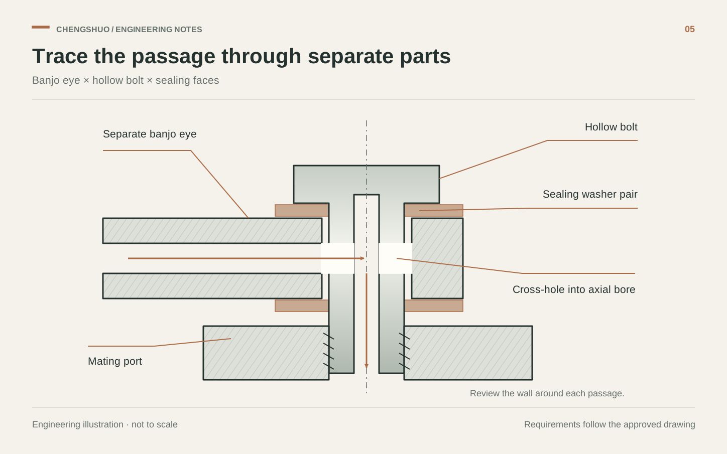
A custom banjo connection may include an eye body, a hollow bolt, sealing elements and a mating port. State which components the machining supplier will make and which will be purchased elsewhere. Parker's banjo fitting literature distinguishes several families with different sealing arrangements and application ratings. That is a useful reminder to identify the exact design basis; visual resemblance does not establish interchangeability. Include an assembled section in the RFQ so the passage route, clamping stack and sealing interfaces are visible before the individual metal parts are quoted.
Draw the connected passage and its permitted sections
Show the axial bore and cross-holes in the hollow bolt, the intended flow space within the eye and the inlet or outlet connection. Define hole diameter, location and the minimum remaining material at the critical intersections. Review the worst permissible combination of hole position, bore size and exterior geometry, including nearby thread roots or reduced sections where applicable. A centreline sketch can clarify the flow route, but it cannot establish the thinnest wall. Ask the assembly designer to provide the required section limits and performance qualification for the actual pressure and service conditions.
Protect the sealing faces through machining and handling
Mark both the surfaces that locate the eye and those that seal, with the selected sealing elements shown in the assembly. Specify the required face geometry and surface condition from the approved connection design. Confirm thread form, engagement and bolt length against the complete stack, then apply the specified final finish in the inspection plan. Keep these interfaces protected during deburring, cleaning and packing. A visually polished exterior is not a substitute for the defined sealing surface, and an unreviewed washer substitution can change the assembly even when every machined dimension remains unchanged.
Plan access to the internal intersections
Cross-drilling creates edges inside the connected passage that may be difficult to reach. Cogsdill's tooling guidance describes different methods for inaccessible back edges and irregular or intersecting holes, illustrating why access and geometry must be considered when selecting a deburring route. For this part, agree the allowed edge break and how the result will be observed without enlarging a functional opening beyond its limits. Then define cleaning and residual-contamination acceptance separately. A statement that the part was washed records an operation; it does not define which contaminants, particle sizes or residues the receiving inspection will accept.
Illustrative review: a larger cross-hole changes more than area
Suppose an engineering revision enlarges a hollow bolt's cross-hole to investigate a flow restriction while leaving its exterior unchanged. This hypothetical change calls for a fresh section review at the intersection, a check of available deburring access and a repeat of the agreed component inspection. The assembly owner must also decide which functional tests need repeating. Do not assume a larger hole improves the completed connection: the eye passage, neighbouring features and operating conditions remain part of the system. Retain the approved revision so a later repeat order cannot accidentally mix old and new bolt geometry.
Send the connection section with the component drawings
For a Chengshuo machining review, send the eye and hollow-bolt drawings with their assembly section and identify the supplied-part boundary. The quotation can then address the required turning, cross-drilling, inspection and handling scope. Include these details before requesting samples.
- Component and assembly revisions, selected seal and mating-port definition.
- Passage sizes, positions, critical remaining sections and approved material.
- Sealing-face requirements, thread engagement and final surface condition.
- Internal-edge limits, inspection access, cleaning and packaging acceptance.
- Sample records and separately agreed leak, pressure or flow qualification scope.
FROM THE GUIDE TO YOUR PART
Put the checks into context.
Request a drawing review
References & further reading
- Parker Hannifin — Banjo fittings and connection-family differences

- Cogsdill — Deburring catalogue: back edges, irregular surfaces and intersecting holes
General planning guidance. Feasibility and acceptance criteria are confirmed against your drawing.