 4 min read
Name the installation method before choosing the knurl
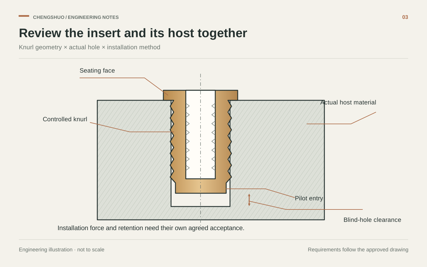
A brass insert with a textured exterior might be intended for cold pressing, heat installation, ultrasonic installation or moulding in place. Those routes should not be treated as interchangeable because the part photographs look similar. This review concerns press-in inserts in plastic hosts. SPIROL describes this type as entering a straight hole without first melting the plastic, with a pilot that helps start insertion squarely. Put the intended method on the RFQ and provide the host drawing. A quotation for the insert alone leaves the most important mating feature outside the discussion.
Specify the plastic and the actual hole
SPIROL's design guide identifies hole size, plastic boss dimensions and material behaviour as contributors to insert performance. It warns that an oversized hole reduces retention, while an undersized hole can create excessive stress and cracking. Select the host dimensions using guidance for the exact insert design and polymer, then validate the proposed combination. For a custom project, record whether the hole is moulded or machined, the resin grade and filler content, the specified conditioning state and the available wall around the hole. Do not copy a hole value from a visually similar insert.
Make the knurl a controlled feature
The machining drawing should identify the over-knurl diameter, knurl form and direction, active band length, pilot, end faces and internal thread. Define the measurement method for the knurled surface so that supplier and receiving inspection compare the same feature. Specify which surfaces must remain free of loose material after manufacture, and whether a finish changes the accepted dimensions. A generic instruction to knurl the outside allows different profiles to be supplied against the same drawing. Keep the selected profile linked to the assembly trial instead of substituting an available shop tool without approval.
Illustrative review: unchanged insert, changed plastic
Suppose a purchasing team changes an enclosure from an unfilled polymer to a glass-filled grade while retaining the same insert and nominal host hole. This hypothetical change should reopen the joint review even though the metal drawing has not changed. Record the new host material, actual hole limits and installation condition before comparing trial assemblies. Examine seating, host damage and the specified torque and pull-out results using the agreed procedure. The useful conclusion is which combination was tested; it is not that one successful insertion proves every enclosure revision will behave the same way.
Separate installation control from retention acceptance
For the trial, identify the insertion tool, support under the boss, alignment and target seating position. Agree whether force-versus-displacement recording would help detect an abnormal insertion, and define what happens to a part with an unusual trace. Such a trace describes the installation event; it does not replace the required retention tests. Also verify screw length and usable thread engagement in the assembled stack, including clearance beneath a blind insert or host hole. Preserve host and insert lot identities so that a later dimensional or material change can be reviewed against the correct trial.
Request a quote for a defined insert-and-host combination
Chengshuo can review the proposed metal component against your controlled drawing and assembly requirements. Send the host information with that drawing so the manufacturing questions are visible before sample release. A useful request includes the following details.
- Insert drawing, thread specification, knurl definition, pilot and accepted finish.
- Plastic grade, filler content, host-hole limits, boss wall and hole-making route.
- Cold-press installation method, support, alignment and target seated position.
- Screw engagement, blind-hole clearance and mating-component stack.
- Trial quantities, torque/pull-out acceptance procedure and revision traceability.
FROM THE GUIDE TO YOUR PART
Put the checks into context.
Request a drawing review
References & further reading
- SPIROL — Press-in inserts: method, pilot and helical knurl

- SPIROL — Threaded Inserts for Plastics Design Guide, insert and host design
General planning guidance. Feasibility and acceptance criteria are confirmed against your drawing.