 4 min read
Identify what closes against what
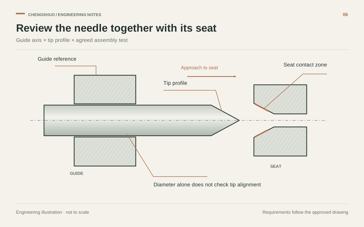
A needle valve stem is more than a slender turned shaft. Its tip works with a particular seat, while the guide and actuation mechanism control how those surfaces meet. Swagelok describes flow-control designs with engineered stem-tip geometry fitting into a seat, and separately documents nonrotating-stem valves. For a custom component, begin with an assembly section showing whether the tip rotates, where the stem is guided and which surfaces form the intended contact. The word needle alone does not define the machining requirement or the acceptance test. Mark the required contact zone before choosing a manufacturing route.
Control the tip profile and the seat geometry
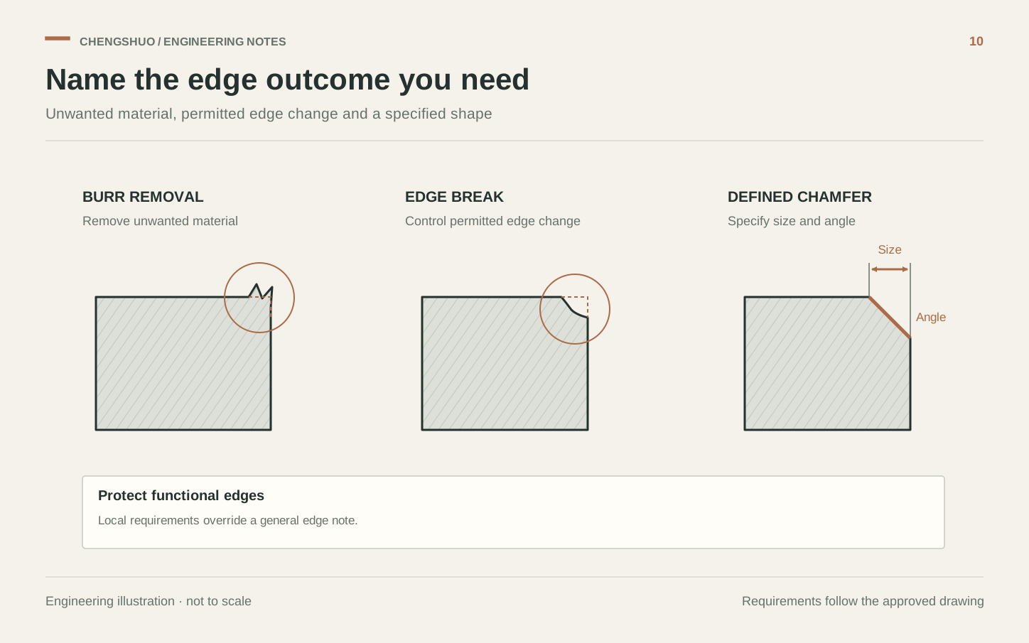
Specify the tip angle, profile or radius with limits, together with the axial location that matters in the assembly. State whether an angle is included or measured from the axis; a sketch can prevent a costly interpretation error. On the mating seat, define the bore, entry geometry and intended contact band. Do not assume that two nominally equal cone angles establish an acceptable seal. Any intentional angle difference, lapping operation or matched-pair requirement belongs in the approved design and purchasing scope. Protect a functional tip from an unrestricted general edge-break note.
Replace vague concentricity language with a drawing requirement
Ask which feature establishes the working axis: a guide diameter, a bearing interface or another nominated datum feature. Then have the drawing owner select the geometric control that expresses the intended relationship between that reference and the tip. A diameter check alone cannot demonstrate this relationship. The term concentric is not enough to choose a tolerance or inspection method. Agree the datum setup, controlled surface and evaluation method before samples are made. If the thread merely advances the stem, do not automatically use its outside diameter as the inspection reference for the sealing geometry.
Keep a machined-part report separate from a valve test
The component report can cover the specified profile, locating diameters, geometric relationships, finish and edge condition. A leakage or metering result requires the defined assembly and test procedure. Record the test medium, pressure conditions, temperature, direction, stabilisation period, measurement method and acceptance limit where applicable. The design owner should also define closure or actuation conditions. Otherwise, different seating loads can make apparently similar results incomparable. Chengshuo can review a drawing-led machining request; any assembled valve test, special finishing operation or external laboratory work needs to be identified and agreed in the quotation.
Example: one needle, two different release decisions
Consider an illustrative stainless stem with a conical tip, guide diameter and actuation thread. Engineering wants the tip aligned with the guide and free of handling damage; procurement also asks for a leak-tight valve. The first requirement belongs in the component drawing and inspection plan. The second needs the mating seat, assembly procedure and an agreed test. Before quoting, flag a missing tip profile limit or undefined closure condition. Resolving those omissions is more useful than promising a tighter general diameter tolerance. This example describes a review method, not a tested Chengshuo valve.
Send a tip-and-seat review package
Send Chengshuo both component drawings or an assembly section with the RFQ. Identify whether the order covers the stem, seat or a matched set, and separate sample qualification from routine lot release. The review should return a defined machining scope and a list of unresolved functional requirements.
- Provide tip and seat profiles, material grades and drawing revisions.
- Identify guide datums, geometric controls and critical surface requirements.
- Define protected edges, cleaning and individual tip protection in packaging.
- State whether matching, lapping or assembly testing is required.
- Attach the approved functional test method, sample quantity and acceptance limits.
FROM THE GUIDE TO YOUR PART
Put the checks into context.


References & further reading

General planning guidance. Feasibility and acceptance criteria are confirmed against your drawing.