

 6 min read
A center hole is a defined feature at the end of a shaft that may be used to support or locate the part between centers. Before ordering a turned shaft, specify the hole's purpose, form and required condition so the supplier can review the same feature that your drawing intends.
A tapered recess in a photograph is not a complete center-hole specification. The purchasing question is practical: does the feature support a manufacturing operation, a measurement setup or a function of the delivered assembly? That answer affects what needs to be drawn, preserved and checked.
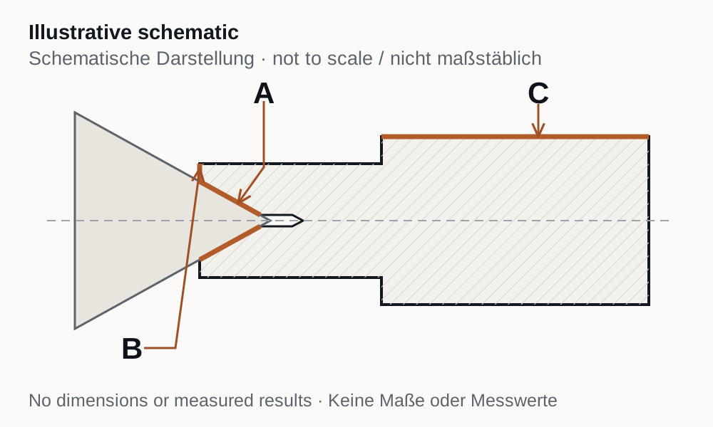
A — Support surface. B — End face. C — External functional diameter. Identify the requirements for each zone on your own drawing.
Separate the part feature from the tool
The center hole belongs to the workpiece. A center drill is a tool that produces a particular geometry. Gühring's public guidance describes center holes at shaft ends for support between centers; its Form A product information also identifies the workpiece center-hole form separately from the tool specification.[1][2]
For your order, identify the required feature on the drawing. If a standard form is specified, state the applicable standard and edition together with the information needed to select its size. A tool catalogue designation does not, by itself, define every requirement for the delivered shaft. In particular, do not copy a cutting-tool point angle into the part callout without checking what that angle describes.
Decide what must remain on the finished shaft
Start with the role of the hole. A feature used during manufacture may be removed by a later operation; another design may require it to remain for subsequent support or inspection. The supplier needs to know which condition your released drawing requires.
Show the surrounding end-face geometry and any nearby thread, bore or assembly interface. If the shaft end later enters a housing, receives a fastener or forms part of a sealing arrangement, include the relevant permitted interface information. Do not leave the final condition to be inferred from a previous sample when that sample was supplied at a different manufacturing stage.
An illustrative example is a shaft that is supported between centers during finishing, then supplied with an end face used by the customer's assembly. The review must resolve whether the support feature remains, is removed or is limited by another end-face requirement. This is a planning example, not a reported Chengshuo job.
Keep support and datum requirements distinct
A center hole can be part of the arrangement used to hold a shaft. That does not automatically make it the drawing datum for every characteristic on the shaft. The drawing and agreed inspection method must identify how the functional diameters, shoulders and other features are evaluated.
For a runout or relationship check, name the feature being measured and the reference used to establish the setup. Discuss the part condition and how it is supported. A result taken in one setup should not quietly be presented as a result for a different datum arrangement. The existing shaft runout and datum guide explains that wider review.
Inspection of the center hole itself is a separate task. If its form, size, surface or edge condition needs recorded acceptance, identify that characteristic and the required coverage. Using the feature to support another measurement does not supply all of those results.
Use this center-hole review checklist
| Review item | Information to provide | Question to close before release |
|---|---|---|
| Purpose | Manufacturing support, inspection support or delivered-part function | At which stage is the feature needed? |
| Definition | Drawing reference, required form, dimensions and any standard edition | Which document controls the center hole? |
| End-face interfaces | Nearby bores, threads, faces and permitted mating information | Can the support feature remain in the delivered geometry? |
| Part condition | Heat treatment, finishing sequence and final acceptance state, when specified | In which condition is the feature checked? |
| Evidence | Characteristic identification, method and locations needing records | What must be recorded separately from the shaft's other checks? |
If an item is unresolved, label it as a question for review. Do not fill in a standard form or a nominal dimension merely to make the enquiry appear complete. Keep the eventual answer with the same drawing revision as the quotation.
Connect the feature to a machining review
Use the part's complete geometry to discuss the route. The CNC turning capability page and Swiss-type CNC turning page provide two existing process entry points. Neither route should be selected solely because a center hole is visible in a reference image.
For a shaft-shaped reference, see the stainless steel main shaft. Use it to describe the family of geometry you need; your controlled drawing determines the center-hole, material and acceptance requirements for your own part.
Send the drawing revision, material and condition, quantities, center-hole purpose and requested inspection records. State any unresolved end-face requirement explicitly. This gives the manufacturing discussion a defined starting point and keeps a process proposal separate from an approved design change.
Frequently asked questions
Is a center hole the same as a center drill
No. The hole is a workpiece feature; the drill is a tool. The drawing defines the part requirement, while tool choice is reviewed as part of the machining route. Gühring's product information is useful for seeing that distinction.[1][2]
Must the center hole remain in the delivered shaft
That depends on the released drawing and the intended final condition. Specify whether the feature must remain, may remain or must be removed. If another end-face requirement conflicts with it, resolve that question before the manufacturing scope is accepted.
Does a center hole automatically establish the shaft datum
No. The drawing's reference requirements and the agreed measurement setup control how each characteristic is evaluated. State the supporting arrangement when it matters; do not treat the existence of a center hole as a complete datum or inspection instruction.
Is a standard form name enough for an enquiry
Check whether the callout identifies the standard edition, form, required size and final condition. The supplier should not have to infer missing selection information. This article deliberately provides no universal center-hole dimension table or tolerance recommendation.
Review your shaft drawing
Include the center-hole callout with the rest of the shaft definition. Add the material, quantities and checks that affect the manufacturing scope, then request a drawing review.
Sources
[1] Gühring — Center-drill guidance. Public explanation of center-hole support and center-drill terminology, accessed 2026-10-14.
[2] Gühring — Form A center-drill product information. Tool-specific description referring to workpiece center holes; no catalogue dimensions or performance claims are adopted here. Accessed 2026-10-14.
Engineering planning guidance. The machining route, feature requirements and acceptance scope are agreed against your part definition.